hi @msv_zitnik ,
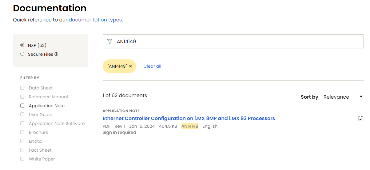
after digging a bit I found a really nice application note from NXP about ethernet controller and I recommend to read it up! I think you will get much better understanding about what is happening under the hood. There is also a patch suggested for RMII mode to work properly by configuring IOMUXC_GPR_GPR1 register properly. You can download it from NXP website AN14149 - Ethernet Controller Configuration on i.MX 8MP and i.MX 93 Processors
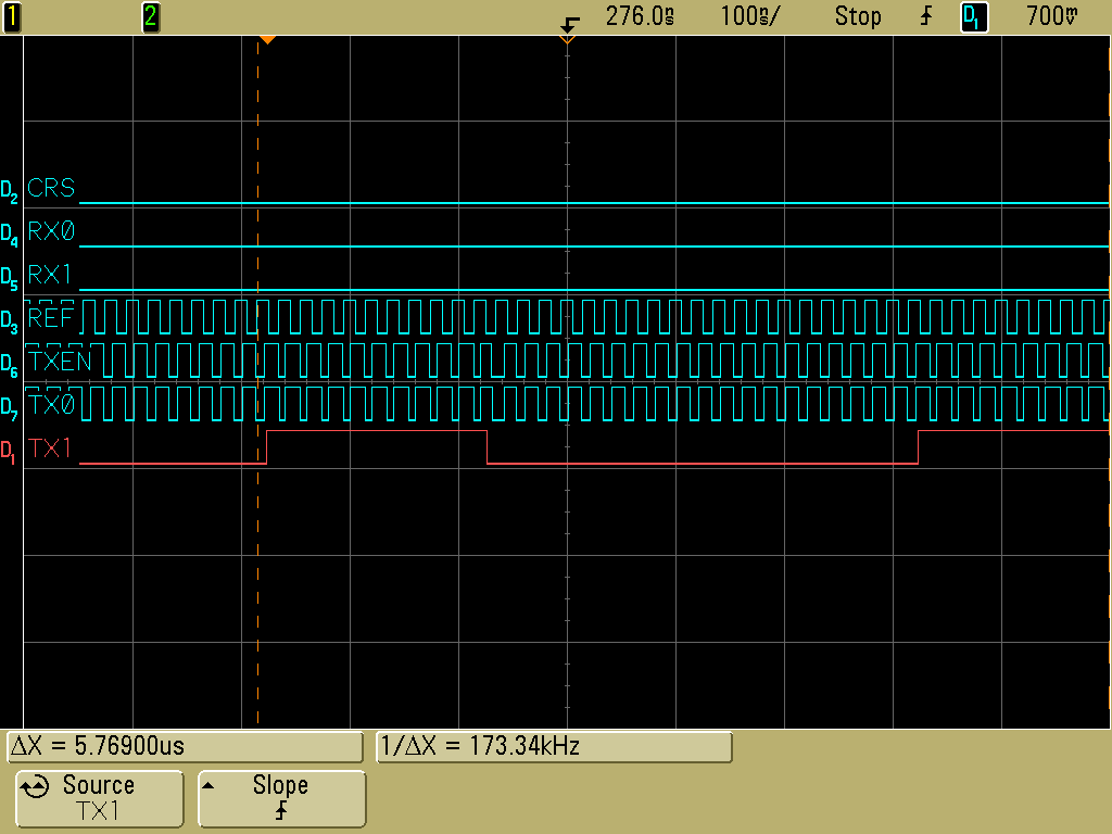
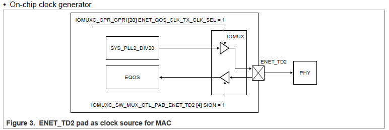
Here is a good depiction of the clock coming from the on-chip generator which is loopback to EQOS controller (the first ethernet. It looks similar for the FEC controller in our case):
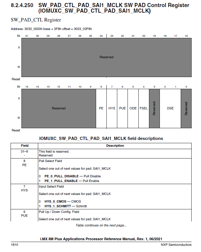
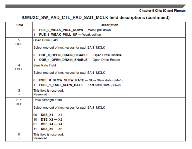
The SYSTEM_PLL2_DIV20 clock source is equivalent with IMX8MP_SYS_PLL2_50M in the device tree to generate 50MHz clock to the pad/pin for the switch and the FEC controller as well and therefore, the SION bit should be put to 1. This is what we do with the value 0x40000000 offset by 16 in this line in the pinctrl_fec node in the device tree:
MX8MP_IOMUXC_SAI1_MCLK__ENET1_TX_CLK 0x40000016
The device tree adjustment needed should look like this:
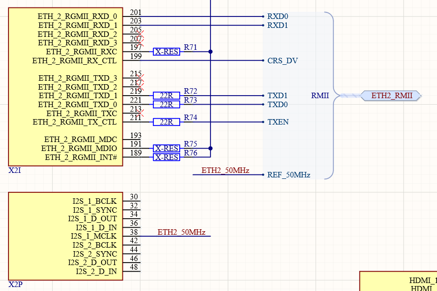
/* Verdin ETH_2_RGMII */
&fec {
	#address-cells = <1>;
	#size-cells = <0>;
	phy-mode = "rmii";
	/delete-property/ phy-supply; //no need; supplied directly from SOM supply
	/delete-property/ phy-handle; //Otherwise, the kernel will log shows an error message about not being able to connect to the PHY

	pinctrl-names = "default";
	pinctrl-0 = <&pinctrl_fec>;

	/* adjusted the clock according to the app note*/
	assigned-clocks =   <&clk IMX8MP_CLK_ENET_AXI>,
						<&clk IMX8MP_CLK_ENET_TIMER>,
						<&clk IMX8MP_CLK_ENET_REF>,
						<&clk IMX8MP_CLK_ENET_PHY_REF>;
	assigned-clock-parents =    <&clk IMX8MP_SYS_PLL1_266M>,
								<&clk IMX8MP_SYS_PLL2_100M>,
								<&clk IMX8MP_SYS_PLL2_50M>;
	assigned-clock-rates = <0>, <100000000>, <50000000>;

	fixed-link {
			speed = <100>;
			full-duplex;
	};

	/* I took this device tree as example: https://git.toradex.com/cgit/linux-toradex.git/tree/arch/arm/boot/dts/imx6qdl-skov-cpu.dtsi?h=toradex_5.15-2.2.x-imx
	This is also a relevant binding: https://git.toradex.com/cgit/linux-toradex.git/tree/Documentation/devicetree/bindings/net/dsa/microchip,ksz.yaml?h=toradex_5.15-2.2.x-imx
	*/
	mdio {
		#address-cells = <1>;
		#size-cells = <0>;

		ksz8873@0 {
			compatible = "microchip,ksz8873";
			reg = <0>;

			/* optional: you can define interrupt signal that can be used by the switch - Pin 41 INTRN on KSZ8873RLL */
			interrupt-parent = <&gpio3>; //are you sure this is the right interrupt line?
			interrupts = <27 IRQ_TYPE_LEVEL_LOW>;
			/* added these properties below according to the app note */
			interrupt-controller;
			#interrupt-cells = <2>;

			/* optional: you can define reset signal that can be used for the switch - Pin 62 RSTN on KSZ8873RLL
			Alternatively, you can use CTRL_RESET_MOCI# on SODIMM 258 as we do it on for our KSZ9131
			refer to page 24 https://docs.toradex.com/109262-verdin-family-specification.pdf to know more about power management feature of our module */
			reset-gpios = <&gpio3 20 GPIO_ACTIVE_LOW>; // I didn't touch this line - make sure you put the right reset line if you need it!

			ports {
				#address-cells = <1>;
				#size-cells = <0>;

				ports@0 {
					reg = <0>;
					phy-mode = "internal";
					label = "lan1";
				};

				ports@1 {
					reg = <1>;
					phy-mode = "internal";
					label = "lan2";
				};

				ports@2 {
					reg = <2>;
					label = "cpu";
					ethernet = <&fec>;
					phy-mode = "rmii";

					fixed-link {
						speed = <100>;
						full-duplex;
					};
				};
			};
		};
	};
};

	/* Connection Carrier Board PHY ETH_2 - I matched the IOMUXC_SW_MUX_CTL_PAD_SAI1_MCLK register value to the ones from application note. If you modified them for your design, feel free to keep them */
	pinctrl_fec: fecgrp {
		fsl,pins = <
			MX8MP_IOMUXC_SAI1_RXD2__ENET1_MDC		    0x2 /* ETH_AUX_MDC */
			MX8MP_IOMUXC_SAI1_RXD3__ENET1_MDIO		    0x2 /* ETH_AUX_MDIO */
			MX8MP_IOMUXC_SAI1_RXD4__ENET1_RGMII_RD0		0x90 /* ETH_AUX_RXD0 */
			MX8MP_IOMUXC_SAI1_RXD5__ENET1_RGMII_RD1		0x90 /* ETH_AUX_RXD1 */
			MX8MP_IOMUXC_SAI1_TXFS__ENET1_RGMII_RX_CTL	0x90 /* ETH_AUX_CRS_DV */
			MX8MP_IOMUXC_SAI1_TXD0__ENET1_RGMII_TD0		0x16 /* ETH_AUX_TXD0 */
			MX8MP_IOMUXC_SAI1_TXD1__ENET1_RGMII_TD1		0x16 /* ETH_AUX_TXD1 */
			MX8MP_IOMUXC_SAI1_TXD4__ENET1_RGMII_TX_CTL	0x16 /* ETH_AUX_TXEN */

			/* I didn't touch the registers given by you below*/
			MX8MP_IOMUXC_SAI1_TXD6__ENET1_RX_ER		    0x00000090 /* ETH_AUX_RXER */
			MX8MP_IOMUXC_SAI1_MCLK__ENET1_TX_CLK		0x40000016 /* ETH_AUX_REFCLK */
			MX8MP_IOMUXC_HDMI_DDC_SDA__GPIO3_IO27		0x00000046 /* !ETH_AUX_INT */
			MX8MP_IOMUXC_SAI5_RXC__GPIO3_IO20   		0x00000006 /* !ETH_AUX_PHY_RESET */
		>;
	};
For the completeness’ sake, this is the patch needed for RMII mode according to the app note:
[…]
+		struct regmap *gpr;
		fec_enet_get_queue_num(pdev, &num_tx_qs, &num_rx_qs);
		/* Init network device */
@@ -4303,7 +4311,14 @@ fec_probe(struct platform_device *pdev)
				goto failed_clk;
		}
		fep->clk_ref_rate = clk_get_rate(fep->clk_ref);
-
+		if((fep->clk_enet_out != NULL)&&(fep->clk_ref != NULL)) {
+				gpr = syscon_regmap_lookup_by_compatible("fsl,imx8mp-iomuxcgpr");
+				if (IS_ERR(gpr)) {
+						dev_err(&pdev->dev, "cannot find iomuxc registers\n");
+						return PTR_ERR(gpr);
+ 				}
+				regmap_update_bits(gpr, 0x4/*IOMUXC_GPR1*/, 0x2000, 0x2000/*bit
13*/);
+		}
Let us know if these work and maybe also what you did to help others here