Enabling second ethernet connection to a fully hardware configured switch IC

Hello Toradex Community,

in my current project im trying to connect the second ethernet to a KSZ8873RLL switch IC. This IC is in our case fully configured in hardware. Therefore our idea was to configure the ethernet connection without the MDIO interface. By now I’ve tested several tipps and guides I could found here and in the NXP forum but nothing changed the behavior of the ethernet at all. I still cant see the second ethernet in ifconfig and nmcli connection show prints out the following

NAME      UUID                                  TYPE      DEVICE    
network0  958cc5e3-1bbf-3d64-beeb-020d4414e254  ethernet  ethernet0 
network1  78c31df4-8c89-31a6-9aeb-d5603e230e4e  ethernet  --  

The latest Topic if checked was this one which is using the same IC:

But, sadly our self developed carrier board has no Debug USB to enter the U-Boot console.

This is my latest DTS configuration:

// Definitions for the FXAS21002C Gyroscope
/dts-v1/;
/plugin/;

#include "imx8mp-pinfunc.h"
#include "imx8mp-clock.h"

&fec {
	fsl,magic-packet;
	fsl,wakeup_irq = <0>;
	pinctrl-names = "default";
	pinctrl-0 = <&pinctrl_fec>;
	phy-mode = "rmii";
	phy-handle = <&ethphyaux>;
	status = "okay";

	mdio {
		#address-cells = <1>;
		#size-cells = <0>;

		ethphyaux: ethernet-phy@7 {
			reg = <7>;
			compatible = "ethernet-phy-ieee802.3-c22";
			max-speed = <100>;
			clocks = <&clk IMX8MP_CLK_ENET_PHY_REF>;
		};
	};
};

&iomuxc {
	/* Connection Carrier Board PHY ETH_2 */
	pinctrl_fec: fecgrp {
		fsl,pins = 
			<MX8MP_IOMUXC_SAI1_RXD4__ENET1_RGMII_RD0		0x00000106>,		/* SODIMM 201 */
			<MX8MP_IOMUXC_SAI1_RXD5__ENET1_RGMII_RD1		0x00000106>,		/* SODIMM 203 */
			<MX8MP_IOMUXC_SAI1_TXFS__ENET1_RGMII_RX_CTL		0x00000106>,		/* SODIMM 199 */
			<MX8MP_IOMUXC_SAI1_TXD0__ENET1_RGMII_TD0		0x00000106>,		/* SODIMM 221 */
			<MX8MP_IOMUXC_SAI1_TXD1__ENET1_RGMII_TD1		0x00000106>,		/* SODIMM 219 */
			<MX8MP_IOMUXC_SD1_DATA4__ENET1_RGMII_TX_CTL		0x00000106>,		/* SODIMM 143 */
			<MX8MP_IOMUXC_SAI1_MCLK__ENET1_TX_CLK			0x00000106>			/* SODIMM  38 */
		;
	};
};

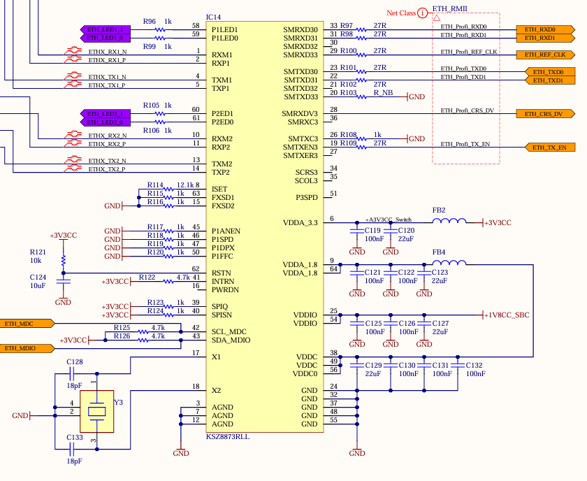
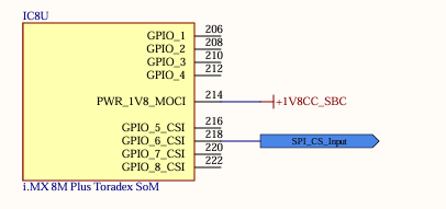
These are the schematics of the ethernet connection:
EthernetLayout.zip (474.5 KB)

tdx-info
Software summary
------------------------------------------------------------
Bootloader:               U-Boot
Kernel version:           5.15.129-rt67-6.5.0-devel+git.d6880bf83a40 #1-TorizonCore SMP PREEMPT_RT Tue Aug 9 12:56:10 UTC 2022
Kernel command line:      root=LABEL=otaroot rootfstype=ext4 quiet logo.nologo vt.global_cursor_default=0 plymouth.ignore-serial-consoles splash fbcon=map:3 ostree=/ostree/boot.1/torizon/4ce36ea31813d045e38a310167f501db776f8d8dce766a449388b74586eb36cd/0
Distro name:              NAME="TorizonCore with PREEMPT_RT"
Distro version:           VERSION_ID=6.5.0-devel-202312-build.20
Distro variant:           VARIANT="Docker"
Hostname:                 verdin-imx8mp-15034173
------------------------------------------------------------

Hardware info
------------------------------------------------------------
HW model:                 Toradex Verdin iMX8M Plus on Verdin Development Board
Toradex version:          0063 V1.1A
Serial number:            15034173
Processor arch:           aarch64
------------------------------------------------------------

dmesg | grep eth
[    0.000000] psci: probing for conduit method from DT.
[    0.835032] imx-dwmac 30bf0000.ethernet: IRQ eth_lpi not found
[    0.836341] imx-dwmac 30bf0000.ethernet: User ID: 0x10, Synopsys ID: 0x51
[    0.836354] imx-dwmac 30bf0000.ethernet: 	DWMAC4/5
[    0.836361] imx-dwmac 30bf0000.ethernet: DMA HW capability register supported
[    0.836366] imx-dwmac 30bf0000.ethernet: RX Checksum Offload Engine supported
[    0.836370] imx-dwmac 30bf0000.ethernet: Wake-Up On Lan supported
[    0.836437] imx-dwmac 30bf0000.ethernet: Enable RX Mitigation via HW Watchdog Timer
[    0.836446] imx-dwmac 30bf0000.ethernet: Enabled L3L4 Flow TC (entries=8)
[    0.836453] imx-dwmac 30bf0000.ethernet: Enabled RFS Flow TC (entries=8)
[    0.836465] imx-dwmac 30bf0000.ethernet: Enabling HW TC (entries=256, max_off=256)
[    0.836474] imx-dwmac 30bf0000.ethernet: Using 34 bits DMA width
[    5.338493] imx-dwmac 30bf0000.ethernet ethernet0: renamed from eth0
[    7.808871] imx-dwmac 30bf0000.ethernet ethernet0: PHY [stmmac-0:07] driver [Microchip KSZ9131 Gigabit PHY] (irq=90)
[    7.816262] imx-dwmac 30bf0000.ethernet ethernet0: Register MEM_TYPE_PAGE_POOL RxQ-0
[    7.816666] imx-dwmac 30bf0000.ethernet ethernet0: Register MEM_TYPE_PAGE_POOL RxQ-1
[    7.817087] imx-dwmac 30bf0000.ethernet ethernet0: Register MEM_TYPE_PAGE_POOL RxQ-2
[    7.817481] imx-dwmac 30bf0000.ethernet ethernet0: Register MEM_TYPE_PAGE_POOL RxQ-3
[    7.817867] imx-dwmac 30bf0000.ethernet ethernet0: Register MEM_TYPE_PAGE_POOL RxQ-4
[    7.826466] imx-dwmac 30bf0000.ethernet ethernet0: No Safety Features support found
[    7.826504] imx-dwmac 30bf0000.ethernet ethernet0: IEEE 1588-2008 Advanced Timestamp supported
[    7.826767] imx-dwmac 30bf0000.ethernet ethernet0: registered PTP clock
[    7.880986] imx-dwmac 30bf0000.ethernet ethernet0: FPE workqueue start
[    7.881000] imx-dwmac 30bf0000.ethernet ethernet0: configuring for phy/rgmii-id link mode
[    9.508346] IPv6: ADDRCONF(NETDEV_CHANGE): ethernet0: link becomes ready
[    9.508524] imx-dwmac 30bf0000.ethernet ethernet0: Link is Up - 100Mbps/Full - flow control rx/tx

I am looking forward to read any kind of tips and guides on how I can solve this issue.

Best regards
KDehren

Hi @KDehren ,

Sorry for the delay in my answer. I had to do a bit of research first myself about the switch since I was not that familiar with this part.

First, I got some questions and remarks:

  1. Are you using our imx8mp-verdin-nonwifi-dev.dts as your base device tree and try to overlay the device tree using your DT overlay?
  2. How did you come up with ethphyaux node and its properties? I would like to understand your line of thought.
  3. You don’t have to use mii tool in U-boot. Linux has an equivalent (and probably better) tool ethtool. This is a good video from TI about it: Using the Linux ethtool and U-Boot MII to examine ethernet link status on Sitara AM-class devices | Video | TI.com
  4. I see that you already have MDIO and MDC lines connected between the switch and the Verdin module. In the KSZ8873 datasheets, I understand it that you need EEPROM or IO strapping for the configuration as unmanaged switch. But, I don’t see any reason not to use the MDIO interface that you already have. Otherwise, I would like to know your thoughts.
  5. How do you power your switch in your carrier board? Can you share your schematic?
    In our Verdin development board, we power on the second Ethernet Phy with power supply which is enabled via GPIO expander using PWR_CTRL_4 signal as shown in the schematic below (more details here). So, we have to make sure that the switch is powered up properly.

OK, now let’s try something with the device tree and I suggest you make the changes in the base .dts and not using overlay. I assume you are using imx8mp-verdin-nonwifi-dev.dts (as to the answer to my first question above). Try to use this device tree instead or modify your custom device tree accordingly (let’s call it my-ksz8873-imx8mp-verdin-nonwifi-dev.dts):

/dts-v1/;

#include "imx8mp-verdin.dtsi"
#include "imx8mp-verdin-nonwifi.dtsi"
#include "imx8mp-verdin-dev.dtsi"

/ {
	model = "My Toradex Verdin iMX8M Plus on Verdin Development Board with KSZ8873";
	compatible = "mytoradex,verdin-imx8mp-nonwifi-dev-ksz8873",
		     "toradex,verdin-imx8mp-nonwifi",
		     "toradex,verdin-imx8mp",
		     "fsl,imx8mp";
};

&fec {
        #address-cells = <1>;
        #size-cells = <0>;
        phy-mode = "rmii";

        /delete-property/ phy-handle; //Otherwise, the kernel will log shows an error message about not being able to connect to the PHY

        fixed-link {
                speed = <100>;
                full-duplex;
        };
}

/* I took this device tree as example: https://git.toradex.com/cgit/linux-toradex.git/tree/arch/arm/boot/dts/imx6qdl-skov-cpu.dtsi?h=toradex_5.15-2.2.x-imx
This is also a relevant binding: https://git.toradex.com/cgit/linux-toradex.git/tree/Documentation/devicetree/bindings/net/dsa/microchip,ksz.yaml?h=toradex_5.15-2.2.x-imx
*/
&mdio{
        /delete-node/ &ethphy1; // we don't need this node which describes KSZ9131RNXI available on our Verdin Dev Board

        #address-cells = <1>;
        #size-cells = <0>;

        ksz8873@0 {
                compatible = "microchip,ksz8873";
                pinctrl-names = "default";
                pinctrl-0 = <&pinctrl_switch>;
                reg = <0>;

                /* Optional: you can define interrupt signal that can be used by the switch - Pin 41 INTRN on KSZ8873RLL */
                interrupt-parent = <&gpio4>; //this will connect to the SODIMM 189 of the module as it is done for KSZ9131 on Verdin Dev Board
                interrupts = <18 IRQ_TYPE_LEVEL_LOW>;
                
                /* Optional: you can define reset signal that can be used for the switch - Pin 62 RSTN on KSZ8873RLL 
                Alternatively, you can use CTRL_RESET_MOCI# on SODIMM 258 as we do it on for our KSZ9131 
                refer to page 24 https://docs.toradex.com/109262-verdin-family-specification.pdf to know more about power management feature of our module */
                reset-gpios = <&gpio1 5 GPIO_ACTIVE_LOW>; //just example - modify or remove
                
                ports {
                        #address-cells = <1>;
                        #size-cells = <0>;

                        ports@0 {
                                reg = <0>;
                                phy-mode = "internal";
                                label = "lan1";
                        };

                        ports@1 {
                                reg = <1>;
                                phy-mode = "internal";
                                label = "lan2";
                        };

                        ports@2 {
                                reg = <2>;
                                label = "cpu";
                                ethernet = <&fec>;
                                phy-mode = "rmii";

                                fixed-link {
                                        speed = <100>;
                                        full-duplex;
                                };
                        };
                };
        };
};

/* if you need these pins to be configured as your original settings above (0x00000106 value for the SW_PAD register) - you can include also here */
&iomuxc {
	/* Connection Carrier Board PHY ETH_2 */
	pinctrl_fec: fecgrp {
		fsl,pins = 
			<MX8MP_IOMUXC_SAI1_RXD4__ENET1_RGMII_RD0		0x00000106>,		/* SODIMM 201 */
			<MX8MP_IOMUXC_SAI1_RXD5__ENET1_RGMII_RD1		0x00000106>,		/* SODIMM 203 */
			<MX8MP_IOMUXC_SAI1_TXFS__ENET1_RGMII_RX_CTL		0x00000106>,		/* SODIMM 199 */
			<MX8MP_IOMUXC_SAI1_TXD0__ENET1_RGMII_TD0		0x00000106>,		/* SODIMM 221 */
			<MX8MP_IOMUXC_SAI1_TXD1__ENET1_RGMII_TD1		0x00000106>,		/* SODIMM 219 */
			<MX8MP_IOMUXC_SD1_DATA4__ENET1_RGMII_TX_CTL		0x00000106>,		/* SODIMM 143 */
			<MX8MP_IOMUXC_SAI1_MCLK__ENET1_TX_CLK			0x00000106>			/* SODIMM  38 */
		;
	};
};

and follow this steps First Steps with Device Trees | Toradex Developer Center. Then run ifconfig -a to check if you can see 2 ethernet interface. Also, can you share the full dmesg log too?

Well, actually we are not quite there yet. Again, we have to make sure that your switch is powered up. So, you probably still need to modify the device tree a bit to supply the power for the switch properly.

I hope the device tree above and the comments are good enough for you to work with.

Let me know if this works for you and share your findings/solution with us.

Also, I found some good references:

Hello @andi.tx

  • Are you using our imx8mp-verdin-nonwifi-dev.dts as your base device tree and try to overlay the device tree using your DT overlay?
    Not by now but I’ve added it to the yaml to test your dts.

  • How did you come up with ethphyaux node and its properties? I would like to understand your line of thought.
    I’ve tried and tested many things. Naming the phy ethphyaux was something I’ve found in another forum and tested for my configuration. Before I’ve also named it ethphy1 without any different results.

  • I see that you already have MDIO and MDC lines connected between the switch and the Verdin module. In the KSZ8873 datasheets, I understand it that you need EEPROM or IO strapping for the configuration as unmanaged switch. But, I don’t see any reason not to use the MDIO interface that you already have. Otherwise, I would like to know your thoughts.
    Once again it is more like a best guess than a reasoned decision. We’ve thought it could make the configuration a bit easier since we are using the RMII interface of a second Switch of this kind with an STM32 controller that does not use the MDIO and MDC lines.

  • How do you power your switch in your carrier board? Can you share your schematic?
    In our Verdin development board, we power on the second Ethernet Phy with power supply which is enabled via GPIO expander using PWR_CTRL_4 signal as shown in the schematic below (more details here). So, we have to make sure that the switch is powered up properly.
    The switch is supplied by the same 3.3V as the SOM itself. In addition to that the VDDIO of the switch is connected to the PWR_1V8_MOCI of the SOM.


    moci

input:
  easy-installer:
    local: images/torizon-core-docker-rt-verdin-imx8mp-Tezi_6.5.0-devel-202312+build.20.tar
customization:
  splash-screen: media/splash-screen.png
  device-tree:
    include-dirs:
      - device-trees/include/
    custom: device-trees/ethernet_toradex.dts
output:
  ostree:
    branch: custom-image-branch
    commit-subject: "SmartWelderVerdinIMX8MP-OS"
    commit-body: "SmartWelderVerdinIMX8MP-OS"
  easy-installer:
    local: images/SmartWelderVerdinIMX8MP-OS
    name: "SmartWelderVerdinIMX8MP-OS-V0.2.3"

I’ve just tested your dts file named ethernet_toradex.dts. To be able to build it I had to move the mdio section into the fec configuration and remove the /delete-node/ &ethphy1; line. If I use the exact same definition I get the following error message.

Building image as per configuration file 'tcbuild.yaml'...

=>> Handling input section
Unpacking Toradex Easy Installer image.
Copying Toradex Easy Installer image.
Unpacking TorizonCore Toradex Easy Installer image.
Importing OSTree revision b46c4e2ebab7338a5ea467de53405ccf8f54b2856fa635aaa96dd76a84c4d756 from local repository...
939 metadata, 9340 content objects imported; 586.8 MB content written                                                                                                       
0 metadata, 0 content objects imported; 0 bytes content written                                                                                                             
Unpacked OSTree from Toradex Easy Installer image:
  Commit checksum: b46c4e2ebab7338a5ea467de53405ccf8f54b2856fa635aaa96dd76a84c4d756
  TorizonCore Version: 6.5.0-devel-202312+build.20

=>> Handling customization section

=> Setting splash screen
splash screen merged to initramfs

=> Handling device-tree subsection

=> Selecting custom device-tree 'device-trees/ethernet_toradex.dts'
Error: device-trees/ethernet_toradex.dts:31.1-6 syntax error
FATAL ERROR: Unable to parse input tree
error: cannot apply device-trees/ethernet_toradex.dts.

Lastly I’ve flashed the changed version of the dts but the SOM did not boot up (No splash-screen, and no connection on any Ethernet possible)

Kind regards,
KDehren

Edit:
I’ve just tested the the yaml with imx8mp-verdin-nonwifi-dev.dts and no further changes. Even there the SOM did not boot-up. Is it possible that using the torizon image with real time patches is causing some issues here?

input:
  easy-installer:
    local: images/torizon-core-docker-rt-verdin-imx8mp-Tezi_6.5.0-devel-202312+build.20.tar
customization:
  splash-screen: media/splash-screen.png
  device-tree:
    include-dirs:
      - device-trees/include/
    custom: device-trees/imx8mp-verdin-nonwifi-dev.dts 

hi @KDehren,

thanky your for your answers. I am sorry, I should have tested/compiled the device tree first beforehand. Can you try this one instead? This one compiled fine for me:

/dts-v1/;

#include "imx8mp-verdin.dtsi"
#include "imx8mp-verdin-nonwifi.dtsi"
#include "imx8mp-verdin-dev.dtsi"

/ {
	model = "My Toradex Verdin iMX8M Plus on Verdin Development Board with KSZ8873";
	compatible = "mytoradex,verdin-imx8mp-nonwifi-dev-ksz8873",
		     "toradex,verdin-imx8mp-nonwifi",
		     "toradex,verdin-imx8mp",
		     "fsl,imx8mp";
};

/delete-node/ &ethphy1; // we don't need this node which describes KSZ9131RNXI available on our Verdin Dev Board

&fec {
        #address-cells = <1>;
        #size-cells = <0>;
        phy-mode = "rmii";
        /delete-property/ phy-supply; //no need; supplied directly from SOM supply
        /delete-property/ phy-handle; //Otherwise, the kernel will log shows an error message about not being able to connect to the PHY

        fixed-link {
                speed = <100>;
                full-duplex;
        };
 
        /* I took this device tree as example: https://git.toradex.com/cgit/linux-toradex.git/tree/arch/arm/boot/dts/imx6qdl-skov-cpu.dtsi?h=toradex_5.15-2.2.x-imx
        This is also a relevant binding: https://git.toradex.com/cgit/linux-toradex.git/tree/Documentation/devicetree/bindings/net/dsa/microchip,ksz.yaml?h=toradex_5.15-2.2.x-imx
        */
        mdio{
                #address-cells = <1>;
                #size-cells = <0>;

                ksz8873@0 {
                        compatible = "microchip,ksz8873";
                        reg = <0>;

                        /* optional: you can define interrupt signal that can be used by the switch - Pin 41 INTRN on KSZ8873RLL */
                        interrupt-parent = <&gpio4>; //this will connect to the SODIMM 189 of the module as it is done for KSZ9131 on VErdin Dev Board
                        interrupts = <18 IRQ_TYPE_LEVEL_LOW>;
                        
                        /* optional: you can define reset signal that can be used for the switch - Pin 62 RSTN on KSZ8873RLL 
                        Alternatively, you can use CTRL_RESET_MOCI# on SODIMM 258 as we do it on for our KSZ9131 
                        refer to page 24 https://docs.toradex.com/109262-verdin-family-specification.pdf to know more about power management feature of our module */
                        reset-gpios = <&gpio1 5 GPIO_ACTIVE_LOW>; //just example - modify or remove
                        
                        ports {
                                #address-cells = <1>;
                                #size-cells = <0>;

                                ports@0 {
                                        reg = <0>;
                                        phy-mode = "internal";
                                        label = "lan1";
                                };

                                ports@1 {
                                        reg = <1>;
                                        phy-mode = "internal";
                                        label = "lan2";
                                };

                                ports@2 {
                                        reg = <2>;
                                        label = "cpu";
                                        ethernet = <&fec>;
                                        phy-mode = "rmii";

                                        fixed-link {
                                                speed = <100>;
                                                full-duplex;
                                        };
                                };
                        };
                };
        };
};

Your issue with TorizonCore Builder seems to be something else, I never heard of that before. Is this happening for the first time?

I think this is related to TorizonCore Builder itself. Try just to put the SOM on our carrier board if it boots. You can at least debug via UART. If it doesn’t work, try to recover your SOM with a new image and maybe try to use non-RT quarterly image (not sure if there is the problem). You can try TorizonCore Builder customisation again. Here is again the documentation, maybe you missed some steps?

Alternatively, you can compile from the source code and copy the ethernet_toradex.dtb to the board by yourself, this is what I did.

If this device tree works, I recommend writing your own device tree that replace imx8mp-verdin-dev.dtsi and probably imx8mp-verdin-nonwifi.dtsi too (unless you have wireless version of your board so you want to keep them separate). Your final .dts will have all modifications or your carrier board and include only imx8mp-verdin.dtsi.

Hello @andi.tx,

I’ve tested your dts file once as overlay and once as custom file.
As overlay the SOM start as expected but there is now hint to the eth1 on dmseg, nmcli or ifconfig.
As custom file the SOM again does not boot. I’ve then plugged the SOM into my Yavia board but again. the SOM does not start. With the Yavia Board I could see that the DSI Reset LED lights up once ever 1-2 minutes.

Best regards
KDehren

Hi @KDehren ,

at least that’s a good that it works as device tree overlay. I am wondering why it doesn’t work as custom dts. Did you keep this line? If yes, please remove.
reset-gpios = <&gpio1 5 GPIO_ACTIVE_LOW>; //just example - modify or remove

Can you access U-boot on Yavia and share the full dmesg log here? Did you also try to recover the module and test on Yavia? If yes, you can try to compile the custom dts without using TorizonCore Builder and enable it on the SOM. Try to do it with Yavia and if it boots, move to your carrier board and test the second ethernet

Hello @andi.tx

just for clarification. I did not confirm that the second ethernet is working in overlay mode. I’ve just said that the SOM is able to boot. There is still no second ethernet available.

I’ve just recovered the Module on Yavia and connected to U-Boot during boot. These are the logs of the boot process as well as from dmesg and dmesg | grep eth

Bootlog.txt (3.8 KB)
dmesg.txt (37.7 KB)
dmesg_eth.txt (2.1 KB)

Best regards
KDehren

hi @KDehren ,

can you share the overlay you use?

Hi @andi.tx

the overlay I’m using is exactly the file you’ve shared above. It is included in the following yaml file:

input:
  easy-installer:
    local: images/torizon-core-docker-rt-verdin-imx8mp-Tezi_6.5.0-devel-202312+build.20.tar
customization:
  splash-screen: media/splash-screen.png
  device-tree:
    include-dirs:
      - device-trees/include/
    custom: device-trees/ethernet_toradex.dts
output:
  ostree:
    branch: custom-image-branch
    commit-subject: "SmartWelderVerdinIMX8MP-OS"
    commit-body: "SmartWelderVerdinIMX8MP-OS"
  easy-installer:
    local: images/SmartWelderVerdinIMX8MP-OS
    name: "SmartWelderVerdinIMX8MP-OS-V0.2.3"

This yaml file was again tested with device-trees/ethernet_toradex.dts as device-tree: custom: as well as device-tree: overlay: add:(with appropriate line breaks). In addition to that I’ve also tested the dts file you’ve shared with the &iomuxc section from my initial dts file as well as from the first version you’ve provided.

One other thing I’m still wondering about regarding the dts is the ETH_REF_CLK displayed in the schematics above. Don’t I have to configure this pin as clock input?

Best regards
KDehren

hi @KDehren ,

sorry, I made another assumption again. Overlay doesn’t work like that. Device Tree Overlay and Device Tree are two different things. So, you can’t just take the code above and deploy it as device tree overlay. Here you can find the documentation about device tree, which covers both: Device Tree Documentation Overview | Toradex Developer Center

Btw now, I compiled and deployed the device tree above and I can confirm that it boots with the correct device tree where the switch is defined and it also shows up when I run ifconfig :

torizon@verdin-imx8mp-15139719:~$ find /sys/firmware/devicetree/ | grep ethernet@ | grep /mdio | grep /compatible
/sys/firmware/devicetree/base/soc@0/bus@30800000/ethernet@30bf0000/mdio/compatible
/sys/firmware/devicetree/base/soc@0/bus@30800000/ethernet@30bf0000/mdio/ethernet-phy@7/compatible
/sys/firmware/devicetree/base/soc@0/bus@30800000/ethernet@30be0000/mdio/ksz8873@0/compatible

torizon@verdin-imx8mp-15139719:~$ ifconfig -a | grep ethernet
ethernet0: flags=4163<UP,BROADCAST,RUNNING,MULTICAST>  mtu 1500
ethernet1: flags=4163<UP,BROADCAST,RUNNING,MULTICAST>  mtu 1500

If I run ifconfig other “standard” device tree it only shows 1 ethernet:

torizon@verdin-imx8mp-15139719:~$ ifconfig -a | grep ethernet
ethernet0: flags=4163<UP,BROADCAST,RUNNING,MULTICAST>  mtu 1500
torizon@verdin-imx8mp-15139719:~$ sudo tdx-info -dt
Password:

Device tree
------------------------------------------------------------
Device tree enabled:      imx8mp-verdin-wifi-dev.dtb
Compatible string:        toradex,verdin-imx8mp-wifi-devtoradex,verdin-imx8mp-wifitoradex,verdin-imx8mpfsl,imx8mp
Device trees available:
                          ethernet_toradex.dtb
                          imx8mp-verdin-nonwifi-dahlia.dtb
                          imx8mp-verdin-nonwifi-dev.dtb
                          imx8mp-verdin-nonwifi-mallow.dtb
                          imx8mp-verdin-nonwifi-yavia.dtb
                          imx8mp-verdin-wifi-dahlia.dtb
                          imx8mp-verdin-wifi-dev.dtb
                          imx8mp-verdin-wifi-mallow.dtb
                          imx8mp-verdin-wifi-yavia.dtb
------------------------------------------------------------

Device tree overlays
------------------------------------------------------------
Overlays enabled:         fdt_overlays=verdin-imx8mp_hdmi_overlay.dtbo verdin-imx8mp_spidev_overlay.dtbo
Overlays available:
                          verdin-imx8mp_dsi-to-hdmi_overlay.dtbo
                          verdin-imx8mp_dsi-to-lvds_panel-cap-touch-10inch-lvds_overlay.dtbo
                          verdin-imx8mp_dsi-to-lvds_panel-lvds-dual-channel-1080p_overlay.dtbo
                          verdin-imx8mp_hdmi_overlay.dtbo
                          verdin-imx8mp_hmp_overlay.dtbo
                          verdin-imx8mp_mezzanine_ov5640-alt-jumpers_overlay.dtbo
                          verdin-imx8mp_mezzanine_ov5640-default-jumpers_overlay.dtbo
                          verdin-imx8mp_mezzanine_panel-cap-touch-10inch-lvds_overlay.dtbo
                          verdin-imx8mp_mezzanine_panel-lvds-dual-channel-1080p_overlay.dtbo
                          verdin-imx8mp_nau8822-btl_overlay.dtbo
                          verdin-imx8mp_ov5640_overlay.dtbo
                          verdin-imx8mp_panel-cap-touch-10inch-dsi_overlay.dtbo
                          verdin-imx8mp_panel-cap-touch-10inch-lvds_overlay.dtbo
                          verdin-imx8mp_spidev_overlay.dtbo
------------------------------------------------------------

Of course, I don’t have the switch to test, but I expect this to work just okay. Your booting issue seems to be something else. Regarding the clock, I am not sure but I expect that it would work as example from Microchip: EVB-KSZ9477 Evaluation Board Schematics, PDF and EVB-KSZ9477/KSZ/linux-drivers/ksz9897/linux-6.1/arch/arm/boot/dts/at91-sama5d3_xplained_ung8071.dts at master · Microchip-Ethernet/EVB-KSZ9477

hi @KDehren ,

how is it going with your development? FYI, we made some progress in the other thread and there is some good information you can look up too: Verdin IMX8MP and KSZ8873 - #17 by andi.tx

Please have a look.

Kind regards,
Andi

Hello @andi.tx

Thank you for your support but, as we are already developing a new prototype revision of our PCB, we’ve decided to use another switch IC.

@msv_zitnik, @msv_hofmann FYI:
One reason for the decision to replace the IC is a silicon bug. As stated in the ERRATA sheet there is a bug in the RMII RX communication that could be solved by delaying the clock by approx… 2ns. This bug caused some package drops in another project what lead us to the decision to replace the IC completely.

Best regards
KDehren

Hi @KDehren ,

thank you for your input regarding the switch IC!

But some/many of the information here is related to the second ethernet controller of SoC itself and therefore, it will still be useful for you regardless of the switch IC you are using.

Kind regards,
Andi

Hi @KDehren,

Could you share the replacement IC that you chose? We managed to get the KSZ working with 0% packet drop, but it would be good to have a backup option…

Hi @msv_hofmann

we’ve replaced the switch with the KSZ9893R but we haven’t tested it yet
In our case the package loss only occurred on RX direction of the RMII interface which is connected to a µController.

Best regards
KDehren