Issue receiving data on IMX8MM UARTs

I’ve been stuck on this problem for a while now and tried dozens of fixes, so I apologize in advance if this all seems a bit scatterbrained.

I am bringing up a custom Toradex image using Yocto for the IMX8MM Verdin SOM. We are using verdin-uart1 (serial@30890000) and verdin-uart2 (serial@30880000) to interface with two separate RS-485 devices running at 921600 baud.

With the current configuration, we are able to send all the data we want and the target devices correctly receive it all. When receiving data back from those devices (depending on how I’ve screwed up the image on any given day), we either drop random chunks of some of the received data (typically 25 or 26 bytes out of the middle of a packet) or are unable to receive any data.

In today’s debugging, the UARTs were configured like this in the relevant .dtsi file:

      uart2: serial@30890000 {
        compatible = "fsl,imx8mm-uart", "fsl,imx6q-uart";
        reg = <0x30890000 0x10000>;
        interrupts = <GIC_SPI 27 IRQ_TYPE_LEVEL_HIGH>;
        clocks = <&clk IMX8MM_CLK_UART2_ROOT>,
           <&clk IMX8MM_CLK_UART2_ROOT>;
        clock-names = "ipg", "per";
        status = "okay";
        linux,rs485-enabled-at-boot-time;
      };

      uart3: serial@30880000 {
        compatible = "fsl,imx8mm-uart", "fsl,imx6q-uart";
        reg = <0x30880000 0x10000>;
        interrupts = <GIC_SPI 28 IRQ_TYPE_LEVEL_HIGH>;
        clocks = <&clk IMX8MM_CLK_UART3_ROOT>,
           <&clk IMX8MM_CLK_UART3_ROOT>;
        clock-names = "ipg", "per";
        status = "okay";
        linux,rs485-enabled-at-boot-time;
      };

With these settings, we can reliably receive single bytes in a simple loopback test by running echo -n -e 'a' > verdin-uart1 on one port and cat verdin-uart2 on the other. I have also configured both UARTs to a “raw” mode with stty -F /dev/verdin-uart1 -ignbrk -brkint -ignpar -parmrk -inpck -istrip -inlcr -igncr -icrnl -ixon -ixoff -icanon -opost -isig -iuclc -ixany -imaxbel -xcase min 1 time 0 (please let me know if there’s a simpler command).

However, when sending two bytes, the second byte is never received by the receiving UART. I can see on an oscilloscope that the UART line of the SOM is indeed receiving the bytes, but somehow the Linux driver/buffer/something is not handling them. When sending more than 2 bytes, any possible combination of letters and characters come through in a jumbled mess (like more than half of the bits are not being received).

This is similar but not exactly consistent with our issue of dropping larger chunks of data, but I believe the device tree configuration is the same in both cases.

Today I also attempted to add a DMA buffer to these UARTs, by adding the line dma-names = "rx", "tx"; into the device declarations. Linux is not able to receive any data in the loopback test with this set, so I’m assuming that either it’s wrong to add there or my DMAs are set up incorrectly.

I would appreciate any advice or recommendations for other tests. Thank you!
Hi @spencerarrasmith,

I’m sorry for the delay. I’m trying to check what’s possibly going on but I couldn’t figure out yet what could be the issue. Before digging into this problem a little further, can you try these device tree parameters to check what is going to change in your errors?

Best Regards,
Hiago.

Hi @spencerarrasmith ,

I didn’t notice any mention of the TX enable line for RS485 operation? I don’t use the verdin, so don’t know the default use of rts/cts for that function (and I guess you’ll have a specific use on your carrier board). You’ve got all kinds of interesting device tree options to mess around with there. You’ll probably want to include that analysis when scoping things.

While “echo” and “stty” can give you results, it’s a bit rough to try and do testing that way. If you’ve already got some application that sets up and uses the serial port as rs485, it might make sense to instrument that in a test mode. There are also a bunch of open source serial test applications out there that include rs485 modes.

I wouldn’t go down the DMA mode yet. I’d try to get reliable back and forth with low baud rates and low packet counts and move up the tree from there.

– Dave

Hello Hiago, thanks for your response.

I have rebuilt the image a few times since this post, but I believe one of my UARTs is working as expected and the other is still not handling received data. Here are my current device tree nodes:

      uart2: serial@30890000 {
        compatible = "fsl,imx8mm-uart", "fsl,imx6q-uart";
        reg = <0x30890000 0x10000>;
        interrupts = <GIC_SPI 27 IRQ_TYPE_LEVEL_HIGH>;
        clocks = <&clk IMX8MM_CLK_UART2_ROOT>,
           <&clk IMX8MM_CLK_UART2_ROOT>;
        clock-names = "ipg", "per";
        status = "okay";
        /delete-property/ dmas;
        /delete-property/ dma-names;
        fsl,dce-mode,rs485-enabled-at-boot-time,linux;
        rs485-rts-active-low;
        rs485-rx-during-tx;
      };

      uart3: serial@30880000 {
        compatible = "fsl,imx8mm-uart", "fsl,imx6q-uart";
        reg = <0x30880000 0x10000>;
        interrupts = <GIC_SPI 28 IRQ_TYPE_LEVEL_HIGH>;
        clocks = <&clk IMX8MM_CLK_UART3_ROOT>,
           <&clk IMX8MM_CLK_UART3_ROOT>;
        clock-names = "ipg", "per";
        status = "okay";
        /delete-property/ dmas;
        /delete-property/ dma-names;
        fsl,dce-mode,rs485-enabled-at-boot-time,linux;
        rs485-rts-active-low;
        rs485-rx-during-tx;
      };

What’s confusing to me is why they would behave differently (board design is identical for the two ports), other than some other device or piece of Yocto modifying the register values somehow.

Hey Dave,

I’m not totally sure what you mean by the TX enable line. The transceiver chip on our board is the LTC2865, and I have confirmed that the RS-485 comms are working from a hardware perspective using a second image meant for a different project that’s partially compatible with this board. The enable pins for that chip have been gpio-hogged to their correct levels.

If you know where I can find all of the “interesting device tree options,” I would appreciate a link. Thus far I have been copying pieces out of examples from around the internet, without any clear plan.

I have created a test utility of my own, but I would also appreciate any links to any of those open source utilities you’ve found useful.

Several of us here are suspicious about how the buffers are being handled in Linux, so adding DMA functionality could have been a workaround for that. I have dropped that effort for now.

I used “TX enable” to refer to the /RE and DE inputs on your transceiver. If you’ve verified that they toggle appropriately based on transmit and receive modes, then I guess you’re good. You didn’t list the gpio hog stuff from your device tree in the original post, so I assume you’re manually moving them around in your application?

The kernel docs have this and this and toradex has this

A pretty good discussion on the board regarding these kinds of things is here:

This code looks promising for testing.

Seems like you might have some sort of DE/RE issue going on or perhaps those lines aren’t tied into the serial driver device tree using things like uart-has-rtscts or rts-gpios? So maybe you’re never really in receive mode so the driver isn’t receiving? Or maybe you’re getting lucky with some sort of default rts/cts behavior and it’s enabling your receiver for a while and then not?

Thank you for the links! Your last paragraph is likely spot on, but I’m not sure what else to try.

Currently my device tree looks like this:

      uart2: serial@30890000 {
        compatible = "fsl,imx8mm-uart", "fsl,imx6q-uart";
        reg = <0x30890000 0x10000>;
        interrupts = <GIC_SPI 27 IRQ_TYPE_LEVEL_HIGH>;
        clocks = <&clk IMX8MM_CLK_UART2_ROOT>,
           <&clk IMX8MM_CLK_UART2_ROOT>;
        clock-names = "ipg", "per";
        status = "okay";
        /delete-property/ dmas;
        /delete-property/ dma-names;
        linux,rs485-enabled-at-boot-time;
        rs485-rts-active-low;
        rs485-rx-during-tx;
        uart-has-rtscts;
      };

      uart3: serial@30880000 {
        compatible = "fsl,imx8mm-uart", "fsl,imx6q-uart";
        reg = <0x30880000 0x10000>;
        interrupts = <GIC_SPI 28 IRQ_TYPE_LEVEL_HIGH>;
        clocks = <&clk IMX8MM_CLK_UART3_ROOT>,
           <&clk IMX8MM_CLK_UART3_ROOT>;
        clock-names = "ipg", "per";
        status = "okay";
        /delete-property/ dmas;
        /delete-property/ dma-names;
        linux,rs485-enabled-at-boot-time;
        rs485-rts-active-low;
        rs485-rx-during-tx;
        uart-has-rtscts;
      };

I did add the RTS and CTS lines to the corresponding pinctrl groups (each group now contains 4 pins), but nothing has changed from a functionality perspective. When communicating with the board from Putty using a USB to RS-485 adapter (115200 baud, defaults for everything else), I am not able to receive any data on the board.

Today I did try communicating with the actual system hardware using our application code, and was right back at square one with random chunks of read data going missing.

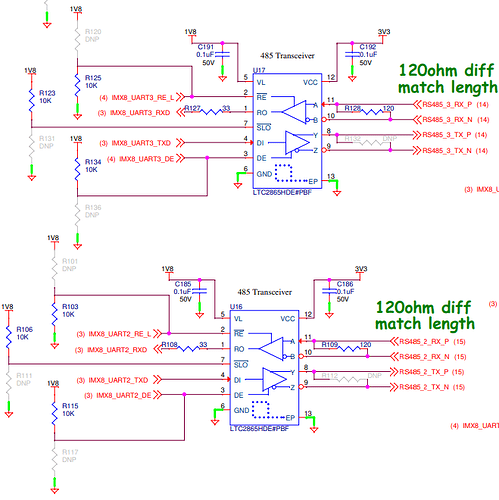
Can you post how you’ve hooked up the DE and RE lines of your transceiver? The gpios involved and whether or not you have other circuitry inline and the gpio device tree pieces for them?

I did not do the board design, but I did confirm that these transceivers work with that other (partially compatible) image. There are no other components between the nets shown here and the processor pins:

Here are the pinctrl groups I’ve defined:

  pinctrl_uart2: uart2grp {
    fsl,pins = <
      MX8MM_IOMUXC_SAI3_TXC_UART2_DCE_TX    0x1c4 /* SODIMM 131 */
      MX8MM_IOMUXC_SAI3_TXFS_UART2_DCE_RX   0x1c4 /* SODIMM 129 */
      MX8MM_IOMUXC_SAI3_RXC_UART2_DCE_RTS_B 0x1c4 /* SODIMM 133 */
      MX8MM_IOMUXC_SAI3_RXD_UART2_DCE_CTS_B 0x1c4 /* SODIMM 135 */
    >;
  };

  pinctrl_uart3: uart3grp {
    fsl,pins = <
      MX8MM_IOMUXC_ECSPI1_MOSI_UART3_DCE_TX   0x1c4 /* SODIMM 139 */
      MX8MM_IOMUXC_ECSPI1_SCLK_UART3_DCE_RX   0x1c4 /* SODIMM 137 */
      MX8MM_IOMUXC_ECSPI1_SS0_UART3_DCE_RTS_B 0x1c4 /* SODIMM 141 */
      MX8MM_IOMUXC_ECSPI1_MISO_UART3_DCE_CTS_B 0x1c4 /* SODIMM 143 */
    >;
  };

A couple of missing pieces you should clarify:

  • Does “IMX8_UART3_RE_L” route to SODIMM 141?
  • Does “IMX8_UART3_DE” route to SODIMM 143?
  • Does “IMX8_UART2_RE_L” route to SODIMM 133?
  • Does “IMX8_UART3_DE” route to SODIMM 135?

I’m also a bit confused now, as it looks like you might be rs-422? Do you have a 4-wire connection between the two devices?

The device tree stuff will need some tinkering. RTS is an output but CTS is an input. Depending on your routing and the rs-485 vs rs-422 piece, you’ll need to change something there. Your transceiver expects outputs driving RE and DE, so you’ll have to use the gpio configured as an output.

If you’re rs-422, you might be able to just set RE low and DE high and avoid all of the rs485/rts/cts device tree stuff altogether.

I’m not an expert in all things RS-422 vs RS-485, but it seems like almost a semantics argument in this case. We have one control board talking to a separate device over a differential serial line, and the board with the Yocto image is the master/controller/driver/etc. We don’t need the sophisticated RTS/CTS flow control here, so maybe the simplest explanation is that it is RS-422.

At the time of the first post in this thread, I had not defined RTS/CTS or RE/DE lines in the pinctrl groups for the UARTs, only the RX/TX pins. That version was not working, and based on your post yesterday I thought this was worth a try. The GPIO pins were also tied high and low respectively at that point, with gpio-hog nodes like you suggested, but I still was not reliably receiving data.

And I apologize for the pinout confusion. I tried for a day to untangle Toradex’s device tree situation with the UARTs but gave up. UART1 becomes verdin-uart3, UART2 becomes verdin-uart1, and UART3 becomes verdin-uart2. Ultimately I care most about the nodes shown in the first post (serial@30890000 and serial@30880000), but if we can get one of them working the other should follow suit. I have a giant table drawn on my whiteboard to keep track of all these pins and remappings, and I quadruple-check them when making changes, so that won’t be an issue on my end.

I’ll revert the RE/DE lines and run some more tests. And thank you for continuing to reply… I know this is a mess.

If you’re just one device talking to another over two differential pairs, then you really have an easier scenario. Your TX pair on one side is wired to the RX pair on the other, and vice versa. You’re full duplex and point-to-point there and really have no need for any type of rs485 or rts/cts stuff. Any mention of rs485 and rts/cts can be removed from the device tree. You just need to make sure that the RE and DE lines are set to always enable RX and TX. You can either drive them by defining them as gpio outputs or just let the external pullup/pulldown take care of business for you (but still make sure those pins are set to inputs). You’ll set the serial port up in raw mode and go to town.

If you’re only one differential pair between the boards, then things change completely. You’re half duplex then and need to worry about the rs485 stuff in the device tree (among other things).

Hi @spencerarrasmith,

Has your issue been solved? Do you still need any help with that?

Best Regards,
Hiago.

No, this issue is not resolved but I had to switch to some other tasks. Most of the company is out of the office this week, and I am out next week. I will resume work on this on January 9.

We were able to hire some outside help to get this resolved. Our Yocto environment was set up to use the 5.4 kernel which does not have IMX8 device tree files. Those files were manually added into the build system by a different engineer who left the company in December 2021.

I believe the version of imx8mm-pinfunc.h we were using came from here: freescale « dts « boot « arm64 « arch - linux-toradex.git - Linux kernel for Apalis, Colibri and Verdin modules

The mux register definitions for the SAI3_TXFS and SAI3_TXC pins (uart2 in the device tree, or verdin-uart1 in sysfs) in the 5.4-2.3 version have four UART options each:

#define MX8MM_IOMUXC_SAI3_TXFS_UART2_DCE_RX                                 0x1D8 0x440 0x000 0x4 0x0
#define MX8MM_IOMUXC_SAI3_TXFS_UART2_DCE_TX                                 0x1D8 0x440 0x4FC 0x4 0x2
#define MX8MM_IOMUXC_SAI3_TXFS_UART2_DTE_RX                                 0x1D8 0x440 0x4FC 0x4 0x2
#define MX8MM_IOMUXC_SAI3_TXFS_UART2_DTE_TX                                 0x1D8 0x440 0x000 0x4 0x0
. . .
#define MX8MM_IOMUXC_SAI3_TXC_UART2_DCE_RX                                  0x1DC 0x444 0x000 0x4 0x0
#define MX8MM_IOMUXC_SAI3_TXC_UART2_DCE_TX                                  0x1DC 0x444 0x4FC 0x4 0x3
#define MX8MM_IOMUXC_SAI3_TXC_UART2_DTE_RX                                  0x1DC 0x444 0x4FC 0x4 0x3
#define MX8MM_IOMUXC_SAI3_TXC_UART2_DTE_TX                                  0x1DC 0x444 0x000 0x4 0x0

but in the master kernel branch (linux/imx8mm-pinfunc.h at master · torvalds/linux · GitHub), only two options are present for each:

#define MX8MM_IOMUXC_SAI3_TXFS_UART2_DCE_RX                                 0x1D8 0x440 0x4FC 0x4 0x2
#define MX8MM_IOMUXC_SAI3_TXFS_UART2_DTE_TX                                 0x1D8 0x440 0x000 0x4 0x0
. . .
#define MX8MM_IOMUXC_SAI3_TXC_UART2_DCE_TX                                  0x1DC 0x444 0x000 0x4 0x0
#define MX8MM_IOMUXC_SAI3_TXC_UART2_DTE_RX                                  0x1DC 0x444 0x4FC 0x4 0x3

We believe that the final value was the culprit, which gives the daisy chain setting for RS-485. Also, because I was seeing strange behavior on both UARTs, I think I had been making the same changes to both (DCE → DTE and back). Given these incorrect pinfunc options, that meant that at least one of them would always be essentially nonfunctional.

Lessons Learned

  • Use up-to-date version of kernel files when possible, or at least generate a diff between your version and the current version to see if any important bugfixes should be made in your version.

  • Document device tree changes and results of the tests

  • Just because it’s a kernel file doesn’t mean it’s bug-free

Hopefully this can help someone in the future!