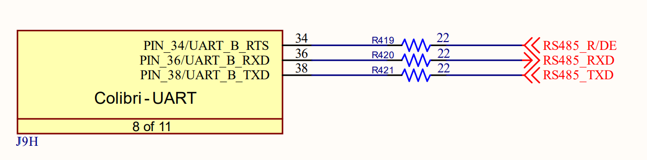
Colibri iMX6 DL 512MB IT
running c code on Torizon
Hi guys
I am stumped by this… wasted 2 days already…
I am able to get my RS485 port to write to a terminal program, so I know I have MOST of my settings correct anyways, for example
9600 baud
1 stop bit
no parity
8 data bits
no flow control
and not so many days ago, I was actually able to get it to read from the serial port as well.
(So this means that at least my device-tree should be in good shape… which is a relief in itself.)
Since then however, I did some major refactoring and broke the program. I was able to roll back to a point where writing to the serial port is working again, but I simply can’t get read() to work agiain.
I can see when I type on the keyboard, that the TxD light on my EasySync RS485-USB adaptor is blinking so there should be data making it to the board. Pretty sure my wires are correct (had A and B flipped a while ago, and RS485 simply doesn’t work if you do that, I have learned)
I have basically simplified my code down to a single function now for debugging purposes, and to share it with you here.
Any ideas what I can be missing?
/* start */
int InitModbus(){
// adapted from https://gist.github.com/amarburg/07564916d8d32e20e6ae375c1c83a995
int err = 0;
unsigned int i = 0;
char buf[80] = {0};
char buf2[80] = {0};
int enable = 1;
// int enable = atoi( argv[2] );
int flags = O_RDWR | O_NOCTTY | O_NONBLOCK;
// int modbusFileDescriptor moved to global variable.
#if DISABLE_MODBUS == 1
#else
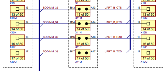
modbusFileDescriptor = open("/dev/colibri-uartb", flags);
if (modbusFileDescriptor < 0) {
/* Error handling. See errno. */
fprintf( stderr, "Error opening port /dev/colibri-uartb (%d): %s\n", errno, strerror( errno ));
//exit(-1);
err |= ERROR_MODBUS;
}
struct serial_rs485 rs485conf;
if (ioctl (modbusFileDescriptor, TIOCGRS485, &rs485conf) < 0) {
fprintf( stderr, "Error reading ioctl port (%d): %s\n", errno, strerror( errno ));
}
printf("Port currently RS485 mode is %s\n", (rs485conf.flags & SER_RS485_ENABLED) ? "set" : "NOT set");
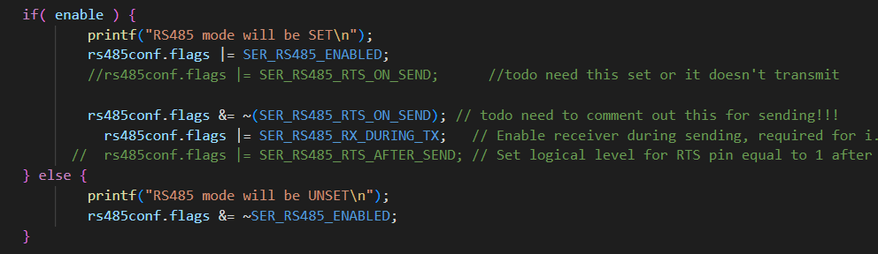
if( enable ) {
printf("RS485 mode will be SET\n");
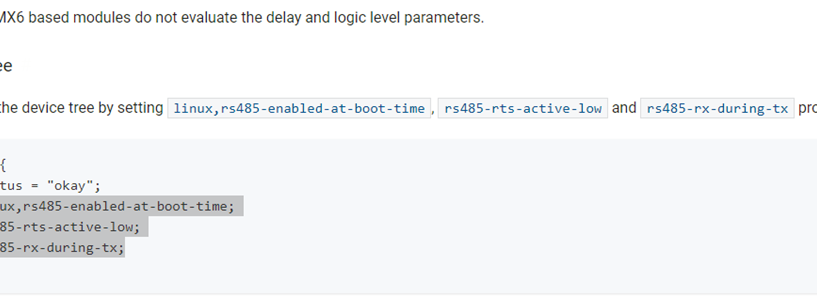
rs485conf.flags |= SER_RS485_ENABLED | SER_RS485_RTS_ON_SEND;
// rs485conf.flags &= ~(SER_RS485_RTS_ON_SEND); //
rs485conf.flags |= SER_RS485_RX_DURING_TX; // Enable receiver during sending, required for i.MX devices
rs485conf.flags |= SER_RS485_RTS_AFTER_SEND; // Set logical level for RTS pin equal to 1 after sending:
} else {
printf("RS485 mode will be UNSET\n");
rs485conf.flags &= ~SER_RS485_ENABLED;
}
if (ioctl (modbusFileDescriptor, TIOCSRS485, &rs485conf) < 0) {
fprintf( stderr, "Error sending ioctl port (%d): %s\n", errno, strerror( errno ));
}
/* Use read() and write() syscalls here... */
if (ioctl (modbusFileDescriptor, TIOCGRS485, &rs485conf) < 0) {
fprintf( stderr, "Error reading ioctl port (%d): %s\n", errno, strerror( errno ));
}
printf("Confirm RS485 mode is %s\n", (rs485conf.flags & SER_RS485_ENABLED) ? "set" : "NOT set");
// SET UP THE RS485 PARAMETERS USING TERMIOS.H
// see: https://blog.mbedded.ninja/programming/operating-systems/linux/linux-serial-ports-using-c-cpp/#basic-setup-in-c
struct termios tty;
// for use with termios tty;
if(tcgetattr(modbusFileDescriptor, &tty) != 0) {
printf("Error %i from tcgetattr: %s\n", errno, strerror(errno));
}
//struct termios2 tty; // must comment out #include termios.h to use this.
// for use with termios2 tty;
// ioctl(modbusFileDescriptor, TCGETS2, &tty); // get the settings
// modify the settings
tty.c_cflag &= ~PARENB; // Clear parity bit, disabling parity (most common)
tty.c_cflag &= ~CSTOPB; // Clear stop field, only one stop bit used in communication (most common)
tty.c_cflag |= CS8; // 8 bits per byte (most common)
tty.c_cflag &= ~CRTSCTS; // Disable RTS/CTS hardware flow control (most common)
tty.c_cflag |= CREAD | CLOCAL; // Turn on READ & ignore ctrl lines (CLOCAL = 1)
tty.c_lflag &= ~ICANON; // In canonical mode, input is processed when a new line character is received... and so we normally want to disable canonical mode.
tty.c_lflag &= ~ECHO; // Disable echo
tty.c_lflag &= ~ECHOE; // Disable erasure
tty.c_lflag &= ~ECHONL; // Disable new-line echo
tty.c_lflag &= ~ISIG; // When the ISIG bit is set, INTR, QUIT and SUSP characters are interpreted. We don’t want this with a serial port, so clear this bit:
tty.c_iflag &= ~(IXON | IXOFF | IXANY); // Turn off s/w flow ctrl (Clearing IXOFF, IXON and IXANY disables software flow control, which we don’t want)
tty.c_oflag &= ~OPOST; // Prevent special interpretation of output bytes (e.g. newline chars)
tty.c_oflag &= ~ONLCR; // Prevent conversion of newline to carriage return/line feed
// tty.c_oflag &= ~OXTABS; // Prevent conversion of tabs to spaces (NOT PRESENT IN LINUX)
// tty.c_oflag &= ~ONOEOT; // Prevent removal of C-d chars (0x004) in output (NOT PRESENT IN LINUX)
tty.c_cc[VTIME] = 10; // Wait for up to 1s (10 deciseconds), returning as soon as any data is received.
tty.c_cc[VMIN] = 0;
// If you want to remain UNIX compliant, the baud rate must be chosen from one of the following:
// B0, B50, B75, B110, B134, B150, B200, B300, B600, B1200, B1800, B2400, B4800, B9600, B19200, B38400, B57600, B115200, B230400, B460800
cfsetispeed(&tty, B9600); // Set in/out baud rate to be 9600
cfsetospeed(&tty, B9600);
//ioctl(modbusFileDescriptor, TCSETS2, &tty); // Now we're done, write terminal settings to the file descriptor.
if (tcsetattr(modbusFileDescriptor, TCSANOW, &tty) != 0) {
printf("Error %i from tcsetattr: %s\n", errno, strerror(errno));
return 1;
}
// make the baud more human-readable..
int baudrate[16393] = {0};
baudrate[B2400] = 2400;
baudrate[B4800] = 4800;
baudrate[B9600] = 9600;
baudrate[B19200] = 19200;
baudrate[B38400] = 38400;
baudrate[B57600] = 57600;
baudrate[B115200] = 115200;
printf("Baud Rate : %d\n", baudrate[tty.c_ospeed]);
if ((tty.c_cflag & PARENB ) == PARENB) {
printf("Parity : ON\n" );
} else {
printf("Parity : OFF\n" );
}
if ((tty.c_cflag & CSTOPB) == 0){
printf("Stop bits : %d\n", 1 );
} else {
printf("Stop bits : %d\n", 2 );
}
if ((tty.c_cflag & CSIZE ) == CS8 ){
printf("Data bits : %d\n", 8 );
} else if ((tty.c_cflag & CSIZE ) == CS7 ){
printf("Data bits : %d\n", 7 );
}
int numBytes = 0;
/* Do something on the serial port... send the values 0 to 100*/
for( i = 0; i < 10000; ++i ) {
snprintf( buf,79, "%d\r\n", i );
write( modbusFileDescriptor, buf, strlen(buf));
printf("%d\n",i);
fflush(stdout);
sleep(1);
if (tcsetattr(modbusFileDescriptor, TCSANOW, &tty) != 0) { // set attributes
printf("Error %i from tcsetattr: %s\n", errno, strerror(errno));
return 1;
}
// if (ioctl (modbusFileDescriptor, TIOCGRS485, &rs485conf) < 0) {
// fprintf( stderr, "Error reading ioctl port (%d): %s\n", errno, strerror( errno ));
// }
memset(buf2,0,sizeof(buf2));
numBytes = read(modbusFileDescriptor, buf2,1);
if (strncmp(buf2,"\0",1) == MATCH) {
printf("numBytes %d\n", numBytes);
// do nothing
} else {
printf("%s\n",buf2);
}
fflush(stdout);
}