Hi @AhmedMobarez,
Let me go through your first answer.
The problem here is that M4 core 0 uses pins 110 and 120 from the SODIMM connector that we only can access using the Evaluation Board.
I’m not aware of any other pins that we can use to debug the core 0 besides M40.UART0.RX and M40.UART0.TX, I checked the datasheet and this function is not available for other pins. However, I’ll test this and reply to you if I find something.
Before we dive into your next question, I was able to use the UART on the Ixora board with the M4 core 1. As I mentioned before, core 0 is not accessible, but for core 1 we can access the pins on the Ixora board.
For that, you can go to /boards/mekmimx8qm/demo_apps/hello_world/cm4_core1/ and compile the hello_world demo. Here, I compiled the debug version (build_debug.sh).
Then, I sent the binary to my Apalis and ran it through uBoot, same as you did, but now you will have to use the commands loadm4image_1, m4image_1, and m4boot_1 to specify that you want to use the M4 core 1.
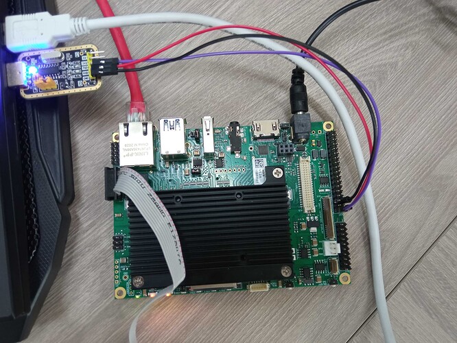
Using a USB to TTL converter, you will see the “hello world.” on pins 35 and 36 from the x27 connector.
Pin 35 will be connected on the Converter RX and 36 to TX. GND will be connected to any GND on Ixora.
Here is my setup:
Then, I made some modifications to the hello_world.c to print a loop of messages:
diff --git a/boards/mekmimx8qm/demo_apps/hello_world/cm4_core1/hello_world.c b/boards/mekmimx8qm/demo_apps/hello_world/cm4_core1/hello_world.c
index 9275fb0..515c0f9 100644
--- a/boards/mekmimx8qm/demo_apps/hello_world/cm4_core1/hello_world.c
+++ b/boards/mekmimx8qm/demo_apps/hello_world/cm4_core1/hello_world.c
@@ -30,8 +30,6 @@
  */
 int main(void)
 {
-    char ch;
-
     /* Init board hardware. */
     sc_ipc_t ipc = BOARD_InitRpc();

@@ -42,9 +40,12 @@ int main(void)

     PRINTF("hello world.\r\n");

+    uint8_t count = 0;
+
     while (1)
     {
-        ch = GETCHAR();
-        PUTCHAR(ch);
+        PRINTF("hello world! %d\r\n", count);
+        if (count == 255) count = 0;
+        else count++;
     }
 }
Now you will see an endless loop of hello worlds. Nest, if you boot the Linux Kernel, you will see that M4 will stop printing on the screen. That’s because Linux Kernel uses those pins for PWM and uart communication, so we need an overlay to disable them:
/dts-v1/;
/plugin/;

/* Disable PWM0 and PMW1 to use M4 Core 1 UART */

/ {
	compatible = "toradex,apalis-imx8-v1.1-eval",
		     "toradex,apalis-imx8-eval",
		     "toradex,apalis-imx8",
		     "fsl,imx8qm";
};

&pwm0 {
    status = "disabled";
};

&pwm1 {
    status = "disabled";
};

&lpuart2 {
    status = "disabled";
};
If you apply this overlay, you will see M4 in an endless loop of prints and you will be able to see Linux Kernel botting without any problems.
Now, let’s go through your next question.
I don’t know what was the problem, maybe you did something wrong with the variables? I’m not sure, I’ll need to test this on my side.
Here I didn’t have any issues either. I can blink the LEDs using Torizon at the same time that M4 is using the pins. I think this is possible because of SCFW, maybe it gives the owner of the GPIO pin when Cortex-A requests it, and then gives it back to M4. However, using the same pin between the two cores can be problematic, I would recommend disabling this pin from the device tree, so Linux will not access it.
I hope this makes things clearer. As I said before, we are updating our Cortex-M documentation, so I’m still testing some features.
Feel free to ask me if you have any further questions.
Best Regards,
Hiago.
