Developing on Apalis Evaluation board and deploying on the Ixora board

Hello everyone,

Following up on this thread , I am considering getting an Apalis Evaluation board for development and debugging as it has the jtag debug interface and then deploying on the Ixora for the end product.

The question here is, if I do that, what do I need to take be careful of ? is there difference in pin naming for example that would make my deployment on the Ixora invalid ?
I would only develop for the peripherals available on the Ixora board, but not sure if the pin names here would be different.

another related question from the previous thread, I am an NXP noobie so I am a bit lost in the reference manual, in this comment, @hfranco.tx clarified that I had the wrong pin assigned

The question is, where can I find this pin name and number, where is it defined that LSIO__GPIO0 and 8U are LSIO.GPIO0.IO8, and LSIO__GPIO0 and 12U are pin LSIO.GPIO0.IO12 (GPIO3) ?

and if this is Ixora specific, where can I find it? and find the Apalis evaluation board related pin definitions ?

Thank you and looking forward to your reply

Hi @AhmedMobarez, how are you?

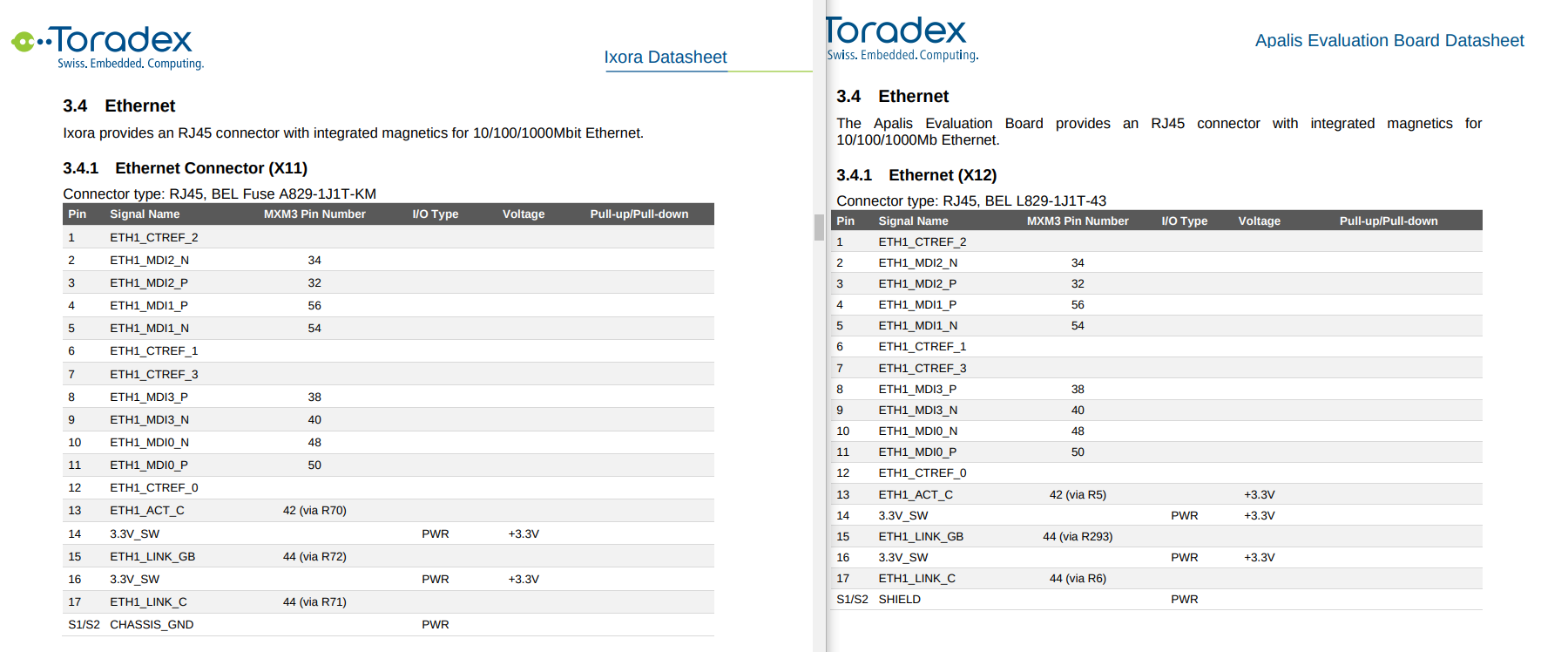
The pin naming is more related to the module itself and not to the carrier board. For instance, take the ethernet example:

Here you can see that the signal names are the same and also the pin numbering.
The main difference is that the Evaluation Board has a few more peripherals available and has all pins exposed so that you can do more testing and debugging in case you want to create your own carrier board.

I’m leaving the datasheets here:

Now talking specifically about the Cortex-M4, the pins are defined inside the pin_mux.c and pin_mux.h files from FreeRTOS. Let’s take the hello world from the core 0 as an example.

If we look at pin_mux.h inside SDK_2_9_0_MIMX8QM6xxxFF/boards/mekmimx8qm/demo_apps/hello_world/cm4_core0, we’ll see these defines:

/* M40_I2C0_SCL (number AM44), FTDI_M40_UART0_RX */
/* Routed pin properties */
#define BOARD_INITPINS_FTDI_M40_UART0_RX_PERIPHERAL                   M40__UART0   /*!< Peripheral name */
#define BOARD_INITPINS_FTDI_M40_UART0_RX_SIGNAL                          uart_rx   /*!< Signal name */
#define BOARD_INITPINS_FTDI_M40_UART0_RX_PIN_NAME                   M40_I2C0_SCL   /*!< Routed pin name */
#define BOARD_INITPINS_FTDI_M40_UART0_RX_PIN_FUNCTION_ID       SC_P_M40_I2C0_SCL   /*!< Pin function id */
#define BOARD_INITPINS_FTDI_M40_UART0_RX_LABEL               "FTDI_M40_UART0_RX"   /*!< Label */
#define BOARD_INITPINS_FTDI_M40_UART0_RX_NAME                "FTDI_M40_UART0_RX"   /*!< Identifier */

Therefore, the RX is using the M40_I2C0_SCL pin for the UART debug. Now looking at the pin_mux.c file, we can see this function:

  err = sc_pad_set_all(ipc, BOARD_INITPINS_FTDI_M40_UART0_RX_PIN_FUNCTION_ID, 1U, SC_PAD_CONFIG_NORMAL, SC_PAD_ISO_OFF, 0x0 ,SC_PAD_WAKEUP_OFF);/* IOMUXD_M40_I2C0_SCL register modification value */

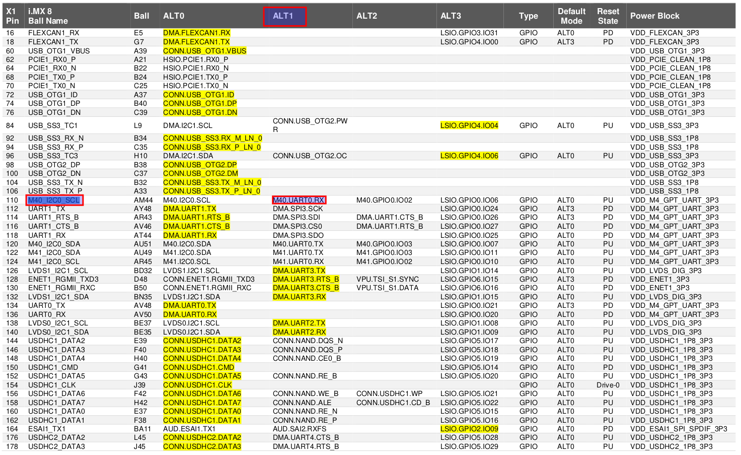
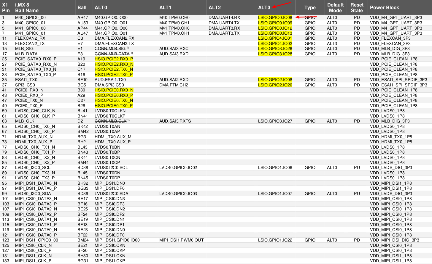
We can see that it is defining the pin M40_I2C0_SCL function 1U. Now looking at the Apalis iMX8 datasheet, we can search for this pin:

As you can see, function 1U (ALT1) is exactly M40.UART0.RX, which is the UART channel used by the Cortex-M4.

You can also see this is pin 110 from the edge connector. Now you can search if this pin is available on the carrier board. For the Apalis Evaluation Board, all pins are available, so you will be able to debug the Cortex-M4 core 0 using this pin. For the Ixora though, the 110 is not available, as I mentioned in this thread.

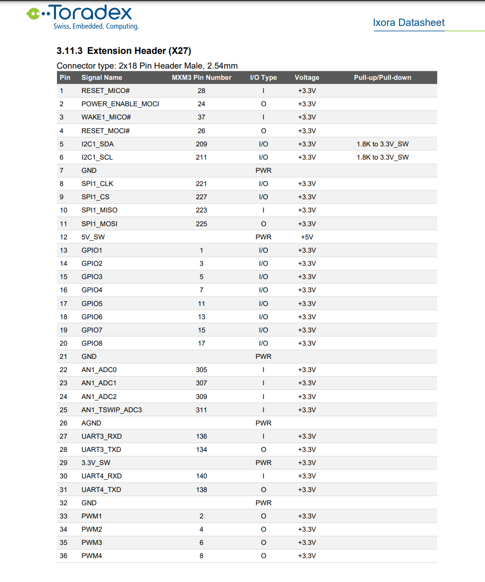
Finally, this is basically what you will need to do in order to develop your application with the Evaluation Board and deploy it to the Ixora board. You will need to search for these pins and make sure all of them are available. Here is the Ixora datasheet: https://docs.toradex.com/107020-ixora-v12-datasheet.pdf

For the Linux side, if you need to configure a pin (for example, changing a function or disabling it from Linux to use with the FreeRTOS), you will need to edit the device tree of the Ixora board.

Please, let me know if this is clear now, and feel free to ask any more questions you might have. We’re improving our documentation on the Cortex-M: High performance, low power Embedded Computing Systems | Toradex Developer Center. We expect to write more articles about it in the next weeks.

Best regards,
Hiago.

Hello Hiago @hfranco.tx ,
I’m great, thanks for asking, and you?
and thanks for the quick reply as always :slight_smile:

I think I understand now, thanks a lot for the clarification, I was actually lost in the 11k pages reference manual from NXP.
But just to make sure I am following, if we take the gpio example from the sdk in SDK_2_9_0_MIMX8QM6xxxFF\boards\mekmimx8qm\driver_examples\gpio\led_output\cm4_core0 in in pin_mux.h the defined LSIO_GPIO3 and 7U are in the following snippet:

/* SPI2_SCK (number AW5), BB_SPI2_SCLK/J20B[18] */
/* Routed pin properties */
#define BOARD_INITPINS_BB_SPI2_SCLK_PERIPHERAL                       LSIO__GPIO3   /*!< Peripheral name */
#define BOARD_INITPINS_BB_SPI2_SCLK_SIGNAL                               gpio_io   /*!< Signal name */
#define BOARD_INITPINS_BB_SPI2_SCLK_CHANNEL                                   07   /*!< Signal channel */
#define BOARD_INITPINS_BB_SPI2_SCLK_PIN_NAME                            SPI2_SCK   /*!< Routed pin name */
#define BOARD_INITPINS_BB_SPI2_SCLK_PIN_FUNCTION_ID                SC_P_SPI2_SCK   /*!< Pin function id */
#define BOARD_INITPINS_BB_SPI2_SCLK_LABEL                "BB_SPI2_SCLK/J20B[18]"   /*!< Label */
#define BOARD_INITPINS_BB_SPI2_SCLK_NAME                          "BB_SPI2_SCLK"   /*!< Identifier */fine BOARD_INITPINS_BB_SPI2_SCLK_GPIO_PIN_MASK                     (1U << 7U)   /*!< GPIO pin mask */

And this is found in this section of the apalis datasheet

which is actually not available in the Ixora board as one of the available GPIOs in the extension header and therefore cannot actually test the default GPIO program with the specified pins

if this is correct then I understood you correctly, thanks again :slight_smile:

one small question, How to switch between ALT0 , ALT1, ALT2 ? it’s still not clear to me where does that 1U or 7U come from

Hi @AhmedMobarez,

happy to help!

yes, you are absolutely right, that’s what you should do to check for compatibility.

The alternates functions are declared inside pin_mux.c, in the snippet that I’ve shown you in my last question. 0U is ALT0, 1U is ALT1, and so on…

Please, pay attention that for GPIO, the definitions below are NOT related to the function of the pin. Although it is defining 7U inside the gpio_led_output.c, this definition means we are selecting the LSIO.GPIO3.IO07 which is still the ALT3 function.

/*******************************************************************************
 * Definitions
 ******************************************************************************/
#define EXAMPLE_LED_GPIO     LSIO__GPIO3
#define EXAMPLE_LED_GPIO_PIN 7U

If we look at pin_mux.c for the GPIO we can see we are still using the ALT3 function:

err = sc_pad_set_all(ipc, BOARD_INITPINS_BB_SPI2_SCLK_PIN_FUNCTION_ID, 3U, SC_PAD_CONFIG_NORMAL, SC_PAD_ISO_OFF, 0x0 ,SC_PAD_WAKEUP_OFF);/* IOMUXD_SPI2_SCK register modification value */

Usually, all GPIOs are under the Function ALT3. For example, if you want to use LSIO.GPIO0.IO08 instead of the default one LSIO.GPIO3.IO07, you only need to change the definition under gpio_led_output.c:

/*******************************************************************************
 * Definitions
 ******************************************************************************/
#define EXAMPLE_LED_GPIO     LSIO__GPIO0
#define EXAMPLE_LED_GPIO_PIN 8U

Because of the LSIO.GPIO0.IO08 is already under the ALT3 function:

If it was inside ALT4, let’s say, you would also have to change the pin_mux.c to 4U.

I hope everything is clear now. Please, let me know if you have any further questions.

Best regards,
Hiago.

Thanks a lot @hfranco.tx ,

This clarified everything I need for now, I can now dig a bit deeper into the code.

Have a great day :slight_smile:

1 Like