mnano
January 16, 2024, 10:28am
1
Hello,
I have been trying to make a 7inch LVDS touch screen work with an iMX8MP connected to an interface board (which follows the design guidelines). I have been unsuccessful so far, the backlight doesn’t even seem to turn on.
Here is some HW information:
Touchscreen controller is an ILITEK ILI251X, and that is activated on Torizoncore
Connected to LVDS0 (so pins 88, 90, …, 114 or MSP_1 to MSP12)
RST_DISP# (Reset display) is connected to SAI3_TXC (I2S_2_BCLK, pin 42)
INT_TOUCH# (Touch interrupt) is connected to SAI3_TXFS (I2S_2_SYNC, pin 44)
BL_ON_SOM (Backlight) is connected to SAI3_TXD (I2S_2_D_OUT, pin 46)
RST_TOUCH# (Reset touch) is connected to SAI3_RXD (I2S_2_D_IN, pin 48)
BL_PWN (Backlight pwm) is connected to PWM_2 (GPIO1_IO11, pin 16)
Touch controller is on I2C_1_SDA/SCL (I2C4_SDA/SCL, pins 12/14)
I already have a working overlay for the same touchscreen but with the DSI-to-LVDS adapter on the Verdin evaluation board. Here is my current version of the overlay for a direct LVDS connection, using the HW information described above:
/dts-v1/;
/plugin/;

/ {
	compatible = "toradex,verdin-imx8mp";
};

#include <dt-bindings/gpio/gpio.h>
#include <dt-bindings/interrupt-controller/arm-gic.h>

&i2c4 {
    touchscreen@41 {
        compatible = "ilitek,ili251x";
        reg = <0x41>;

        interrupt-parent = <&gpio4>;
        interrupts = <25 IRQ_TYPE_EDGE_FALLING>;

        pinctrl-names = "default";
        pinctrl-0 = <&pinctrl_gpio_9_dsi>, <&pinctrl_i2s_2_bclk_touch_reset>;

        reset-gpios = <&gpio5 0 GPIO_ACTIVE_LOW>;

        status = "okay";
    };
};

&backlight {
	status = "okay";
};

&gpu_2d {
	status = "okay";
};

&gpu_3d {
	status = "okay";
};

&lcdif1 {
	status = "okay";
};

&mix_gpu_ml {
	status = "okay";
};

&ml_vipsi {
	status = "okay";
};

&vpu_g1 {
	status = "okay";
};

&vpu_g2 {
	status = "okay";
};

&vpu_vc8000e {
	status = "okay";
};

&vpu_v4l2 {
	status = "okay";
};

&ldb {
	status = "okay";
};

&lvds_channel0 {
    status = "okay";
};

&panel_lvds {
	compatible = "panel-lvds";
	backlight = <&backlight>;
	data-width = <24>;
	data-mapping = "vesa-24";
	height-mm = <86>;
	width-mm = <154>;
	status = "okay";

        // These panel timings work on verdin board with the DSI-to-LVDS connector
	panel-timing {
		clock-frequency = <44900000 51200000 63000000>;
		de-active = <0>;
		hactive = <1024>;
		hback-porch = <160>;
		hfront-porch = <16 160 216>;
		hsync-len = <1 70 140>;
		pixelclk-active = <1>; /* positive edge */
		vactive = <600>;
		vback-porch = <23>;
		vfront-porch = <1 12 127>;
		vsync-len = <1 10 20>;
	};
};

&pwm2 {
	status = "okay";
};
With this overlay, the screen does not work. Nothing is going on and I don’t have immediate access to the serial port to check uboot logs.
Here is the device-tree part of the customization section in my tcbuild.yaml. The file in the overlays directory is the dts shown above:
  device-tree:
    include-dirs:
      - linux/include
    custom: linux/arch/arm64/boot/dts/freescale/imx8mp-verdin-wifi-dahlia.dts
    overlays:
      add:
        - overlays/verdin-imx8mp_panel-cap-touch-7inch-lvds_overlay.dts
        - device-trees/overlays/verdin-imx8mp_spidev_overlay.dts
Is the device tree overlay correct ? Or is there something wrong or something missing ?
Thank you for your help.
Stupid question but did you change the pins? What did you change between using the adapter and not using it?
mnano
January 16, 2024, 3:09pm
3
There was some pins that changed. The latest I tried (without success), which seems to well correspond to the HW I described + guidelines in Display Output, Resolution and Timings (Linux) | Toradex Developer Center + inspiration from verdin-imx8mp_mezzanine_panel-lvds-dual-channel-1080p_overlay.dts:
/dts-v1/;
/plugin/;

/ {
	compatible = "toradex,verdin-imx8mp";
};

#include <dt-bindings/gpio/gpio.h>
#include <dt-bindings/interrupt-controller/arm-gic.h>
#include <dt-bindings/pwm/pwm.h>

#include <../arch/arm64/boot/dts/freescale/imx8mp-pinfunc.h>

&iomuxc {
	pinctrl_touchscreen: touchscreengrp {
		fsl,pins =
			<MX8MP_IOMUXC_SAI3_TXFS__GPIO4_IO31		0x184>,	/* SODIMM 44 */
			<MX8MP_IOMUXC_SAI3_RXD__GPIO4_IO30		0x184>;	/* SODIMM 48 */
	};
};

&i2c4 {
    // Pin 44 (SAI3_TXFS, GPIO4_IO31) > INT_TOUCH#
    // Pin 48 (SAI3_RXD, GPIO4_IO30) > RST_TOUCH#
    touchscreen@41 {
        compatible = "ilitek,ili251x";
        reg = <0x41>;

        interrupt-parent = <&gpio4>;
        interrupts = <31 IRQ_TYPE_EDGE_FALLING>;

        pinctrl-names = "default";
        pinctrl-0 = <&pinctrl_touchscreen>;

        reset-gpios = <&gpio4 30 GPIO_ACTIVE_LOW>;

        status = "okay";
    };
};

// Pin 42 (SAI3_TXC, GPIO5_IO0) > RST_DISP#
// Pin 46 (SAI3_TXD, GPIO5_IO1) > BL_ON
// PWM2 > BL_PWM
&backlight {
    default-brightness-level = <6>;
    pwms = <&pwm2 0 6666667 PWM_POLARITY_INVERTED>;
    status = "okay";
};

&gpu_2d {
	status = "okay";
};

&gpu_3d {
	status = "okay";
};

&lcdif2 {
	status = "okay";
};

&mix_gpu_ml {
	status = "okay";
};

&ml_vipsi {
	status = "okay";
};

&vpu_g1 {
	status = "okay";
};

&vpu_g2 {
	status = "okay";
};

&vpu_vc8000e {
	status = "okay";
};

&vpu_v4l2 {
	status = "okay";
};

&ldb {
	status = "okay";
};

&lvds_channel0 {
	fsl,data-mapping = "spwg";
};

&ldb_phy {
	status = "okay";
};

&panel_lvds {
	compatible = "panel-lvds";
	backlight = <&backlight>;
	data-width = <24>;
	data-mapping = "vesa-24";
	height-mm = <86>;
	width-mm = <154>;
	status = "okay";

	panel-timing {
		clock-frequency = <44900000 51200000 63000000>;
		de-active = <0>;
		hactive = <1024>;
		hback-porch = <160>;
		hfront-porch = <16 160 216>;
		hsync-len = <1 70 140>;
		pixelclk-active = <1>; /* positive edge */
		vactive = <600>;
		vback-porch = <23>;
		vfront-porch = <1 12 127>;
		vsync-len = <1 10 20>;
	};

	port {
		panel_lvds_in: endpoint {
			remote-endpoint = <&lvds_out>;
		};
	};
};

&pwm2 {
	status = "okay";
};
If something is wrong, I just don’t see it. I should be using the right pins.
hello @mnano ,
can you provide us with the datasheet and connection diagram of the display you are using?
Best Regards,
Matthias Gohlke
mnano
January 18, 2024, 8:36am
5
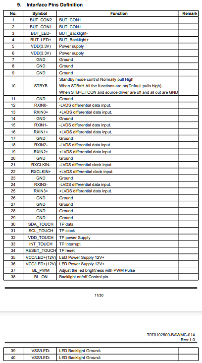
Here is the connection pins for the display being used:
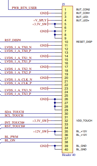
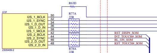
Here is how it’s connected on the schematic:
Obviously there is a bunch a circuitry to between that header and the SoC to properly do the 1.8V → 3.3V conversion.
mnano
January 18, 2024, 2:51pm
6
After measuring BL_PWM and BL_ON (which are PWM_2 and GPIO5_1 / SAI3_TXD) I see them at 0. However, they are both used in backlight on the devicetree, with status “okay”. What am I missing?
mnano
January 23, 2024, 12:19pm
7
I am still stuck at the same stage.
I tried yet another overlay, using the 10" LVDS overlay recently added for the Mellow carrier board (since our board is similar):
// SPDX-License-Identifier: GPL-2.0-or-later OR MIT
/*
* Copyright 2020-2022 Toradex
*/
/dts-v1/;
/plugin/;
#include <dt-bindings/gpio/gpio.h>
#include <dt-bindings/interrupt-controller/arm-gic.h>
#include <dt-bindings/pwm/pwm.h>
/ {
compatible = "toradex,verdin-imx8mp";
};
&{/} {
backlight_lvds_native: backlight-lvds-native {
compatible = "pwm-backlight";
pinctrl-names = "default";
pinctrl-0 = <&pinctrl_i2s_2_d_out_dsi_1_bkl_en>;
brightness-levels = <0 45 63 88 119 158 203 255>;
default-brightness-level = <4>;
power-supply = <®_3p3v>;
/* Verdin I2S_2_D_OUT as GPIO (SODIMM 46) */
enable-gpios = <&gpio5 1 GPIO_ACTIVE_HIGH>;
/* Verdin PWM_2 (SODIMM 16) */
pwms = <&pwm2 0 6666667 PWM_POLARITY_INVERTED>;
status = "okay";
};
panel-lvds-native {
compatible = "panel-lvds";
backlight = <&backlight_lvds_native>;
data-width = <24>;
data-mapping = "vesa-24";
height-mm = <86>;
width-mm = <154>;
status = "okay";
panel-timing {
clock-frequency = <44900000 51200000 63000000>;
de-active = <0>;
hactive = <1024>;
hback-porch = <160>;
hfront-porch = <16 160 216>;
hsync-len = <1 70 140>;
pixelclk-active = <1>; /* positive edge */
vactive = <600>;
vback-porch = <23>;
vfront-porch = <1 12 127>;
vsync-len = <1 10 20>;
};
port {
panel_lvds_native_in: endpoint {
remote-endpoint = <&lvds_out>;
};
};
};
};
&gpu_2d {
status = "okay";
};
&gpu_3d {
status = "okay";
};
&lcdif2 {
status = "okay";
};
&ldb {
status = "okay";
};
&ldb_phy {
status = "okay";
};
&lvds_out{
remote-endpoint = <&panel_lvds_native_in>;
};
&mix_gpu_ml {
status = "okay";
};
&ml_vipsi {
status = "okay";
};
/* Verdin PWM_2 */
&pwm2 {
status = "okay";
};
I just removed all the touch controller related stuff since I am only looking to make this backlight work. Here is some output from the board:
torizon@verdin-imx8mp-14772918:~$ ls -l /sys/class/backlight/backlight-lvds-native/
total 0
-r--r--r-- 1 root root  4096 Jan 23 12:02 actual_brightness
-rw-rw-r-- 1 root video 4096 Apr 28  2022 bl_power
-rw-rw-r-- 1 root video 4096 Apr 28  2022 brightness
lrwxrwxrwx 1 root root     0 Jan 23 11:59 device -> ../../../backlight-lvds-native
-r--r--r-- 1 root root  4096 Apr 28  2022 max_brightness
drwxr-xr-x 2 root root     0 Jan 23 12:02 power
-r--r--r-- 1 root root  4096 Jan 23 12:02 scale
lrwxrwxrwx 1 root root     0 Apr 28  2022 subsystem -> ../../../../../class/backlight
-r--r--r-- 1 root root  4096 Apr 28  2022 type
-rw-r--r-- 1 root root  4096 Apr 28  2022 uevent
torizon@verdin-imx8mp-14772918:~$ sudo cat /sys/kernel/debug/pwm
platform/30670000.pwm, 1 PWM device
 pwm-0   (backlight-lvds-nativ): requested enabled period: 6666667 ns duty: 3111111 ns polarity: inverse
Also with the gpio container:
gpiochip4 - 32 lines:
        line   0:  "SODIMM_42"       unused   input  active-high
        line   1:  "SODIMM_46"     "enable"  output  active-high [used]
I still have nothing even though it seems like I should.
Maybe this is similar to this issue (My interface board is essentially a simplified version of the Mallow carrier board, same pins, see my first message): Nothing on 10.1" LVDS display with Mallow carrier - Technical Support - Toradex Community
Hello @mnano ,
we are looking into this. my colleague will contact you.
Best regards,
Matthias
mnano
January 29, 2024, 8:54am
9
There might be a hardware issue with the level shifter we use. Our supplier just informed us of this and is looking into it. I will close this ticket.
In the meantime I ordered a Mallow carrier board since it has the same pinout and almost the same schematic for the LVDS connection. So I will check my panel and device tree that way. I will open a ticket if I have still have an issue.
Nonetheless, thank you for your attention.
1 Like
Hi @mnano ,
Thanks for letting us know.
If you have more questions, feel free to post them here if they’re related to this one here. If not then kindly open a new question.
We’re here to help.
Best Regards
mnano
March 19, 2024, 3:43pm
11
Hi,
I received a new interface board and the backlight now works.
The only thing is that it seems that the display part is disabled. I wondered how to properly activate it in the device tree.
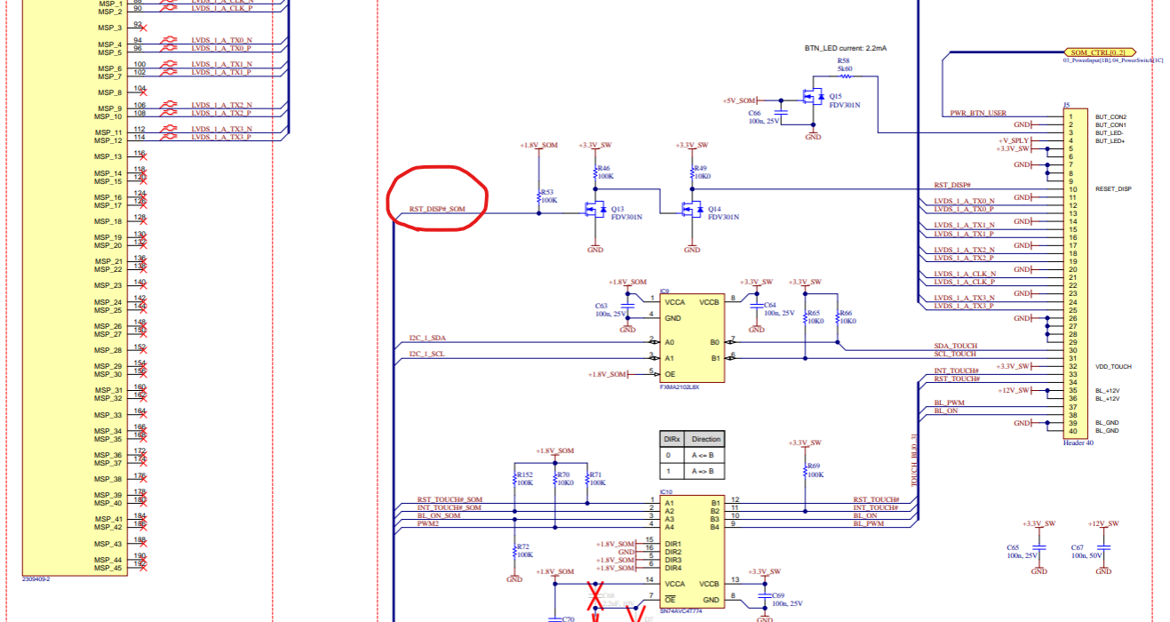
Here is the relevant schematic parts:
The backlight and touchpanel work. It is just that the display shows nothing even though it does on the Marrow carrier board (same pinouts more or less except this reset display pin)
I have this in my devicetree:
&{/} {
backlight_lvds_native: backlight-lvds-native {
compatible = "pwm-backlight";
pinctrl-names = "default";
pinctrl-0 = <&pinctrl_i2s_2_d_out_dsi_1_bkl_en>;
brightness-levels = <0 45 63 88 119 158 203 255>;
default-brightness-level = <4>;
power-supply = <®_3p3v>;
/* Verdin I2S_2_D_OUT as GPIO (SODIMM 46) */
enable-gpios = <&gpio5 1 GPIO_ACTIVE_HIGH>;
/* Verdin PWM_2 (SODIMM 16) */
pwms = <&pwm2 0 6666667 PWM_POLARITY_INVERTED>;
status = "okay";
};
panel-lvds-native {
compatible = "panel-lvds";
backlight = <&backlight_lvds_native>;
data-width = <24>;
data-mapping = "vesa-24";
height-mm = <86>;
width-mm = <154>;
status = "okay";
		/* Verdin I2S_2_BCLK as GPIO (SODIMM 42) */
		pinctrl-names = "default";
		pintctrl-0 = <&pinctrl_i2s_2_bclk_touch_reset>;
		reset-gpios = <&gpio5 0 GPIO_ACTIVE_LOW>;
panel-timing {
clock-frequency = <44900000 51200000 63000000>;
de-active = <0>;
hactive = <1024>;
hback-porch = <160>;
hfront-porch = <16 160 216>;
hsync-len = <1 70 140>;
pixelclk-active = <1>; /* positive edge */
vactive = <600>;
vback-porch = <23>;
vfront-porch = <1 12 127>;
vsync-len = <1 10 20>;
};
port {
panel_lvds_native_in: endpoint {
remote-endpoint = <&lvds_out>;
};
};
};
};
I am not sure about this part in panel-lvds:
/* Verdin I2S_2_BCLK as GPIO (SODIMM 42) */
pinctrl-names = "default";
pintctrl-0 = <&pinctrl_i2s_2_bclk_touch_reset>;
reset-gpios = <&gpio5 0 GPIO_ACTIVE_LOW>;
Is it correct ?
With the gpio container from torizon and gpioinfo I get this:
gpiochip4 - 32 lines:
        line   0:  "SODIMM_42"      "reset"  output   active-low [used]
        line   1:  "SODIMM_46"     "enable"  output  active-high [used]
Hello @mnano ,
please send your schematic as PDF to our support email address.
Best Regards,
Matthias Gohlke
mnano
March 21, 2024, 7:30am
13
Hello,
I sent a mail to the support address with the schematic as PDF and refered to this ticket.
Best regards,
mnano
March 21, 2024, 1:27pm
14
Hello,
I managed to make it work:
I had a typo in the device tree: pintctrl-0 = <&pinctrl_i2s_2_bclk_touch_reset>; → pinctrl not pintctrl.
Despite what I thought, the reset-gpios had to be GPIO_ACTIVE_HIGH and not GPIO_ACTIVE_LOW
Best regards,