I have some questions about how to wire a custom cable to connect the display pannel AUO G133HAN01.0 to a Colibri iMx8 Module through the Iris Carrier Board.
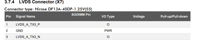
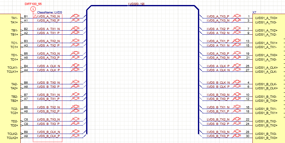
As I can see in the Iris Carrier Board 2.0 datasheet, there is a dedicated LVDS connector with pin designators named as “LVDS_A_TX0_P”.
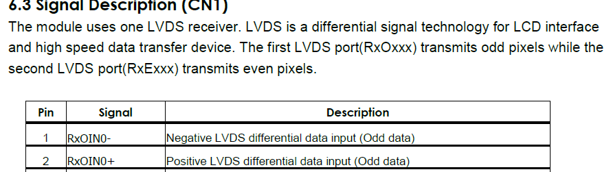
What does it means odd and even in this case? I have supposed that A correspond with ODD, and B with even for channles and clocks signals. Is this correct?
Also there is a chronogram with the input data format in pannel datasheet.
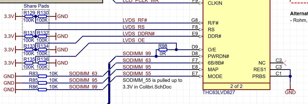
The Iris v2.0 board has an THC63LVD827 LVDS transmitter which converts module’s Parallel RGB output to LVDS. That transmitter can be configured to different modes using Colibri GPIO. Please refer to the THC63LVD827 documentation and Iris board schematic for details.
Sorry but I don’t know purpose of the AGBSEN signal. Please contact display manufacturer.
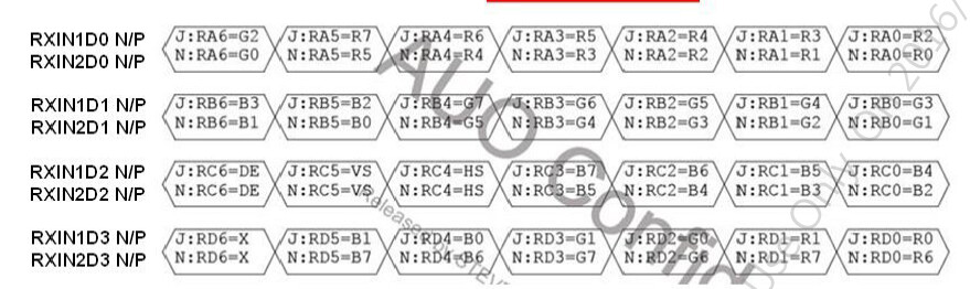
As I can see in the schematics from Iris Board, the channels seem to be in the same order, so I will try like that.
Please, could you refer me to additional information or point me to what else do I need to know to configure the video signal from an iMX8X board connected to Iris.
Lets first clarify a few technical things before we dive into the setup. I just want to make sure that we go the right path here since there are multiple options.
since you are mentioning the colibri IMX8x are you aware that the colibri imx8x has a native LVDS port?
So this means that there are two ways to to connect a LVDS Display to the Iris carrier board and to the SOM itself. If you want to be compatible with the Colibri SOM family you should use the way with the RGB to lvds converter like on the IRIS board. But you will be limited to 18bit if you want to use other colibri module from the colibri family. The colibri family does only specify a 18bit standard.
Please read page 38 and following in the colibri imx8x https://docs.toradex.com/105670-colibri-imx8x-datasheet.pdf “The ColibriiMX8Xprovides one parallel LCD interfaceon the SODIMMconnector. Itsupportsup to 24-bitcolorsper pixel.Only the 18-bit mode is ensured to be compatible with other Colibri modules. The additional signals required for the 24-bit interface are located as alternate functions,which are not located at the same place as on other Colibri modules with 24-bit color support. We recommend using the LCD interface of the Colibri iMX8X only in the 18-bit mode.”
see more also here: Carrier Board Design Guides | Toradex Developer Center
colibri copatibility guide
Are you intending to use the Iris 2.0 in production or just for evaluation? Or are you planning to build you own carrier? So depending on this the approach will be different.
please give me a quick feedback and then we proceed from there.
We are planning to use the iMX8 and Iris carrier board together in short to medium term. It is not possible we use another SOM different from the iMx8 in any case.
With this set up and using the Iris connector, can we assure 24bits depth? Could you guide us from here a bit on how to make both the connection and the software configuration?
I understand that in case of using the LVDS connector from the iMX8 is neccesary to use an adapter. It is right? Then, with Colibri board in our set up there is no advantage to take that approach.
Like I said if you want true 24 bit depth with the colibri imx8x you need to build you own custom carrier board, or you have to build and adapter that takes the 24Bit LVDS output that is available only on the IMX8X via the FFC connector that can also output MIPI DSI(x2).
Or if you fine connecting a 24 bit lvds display but only showing 18bit depth pictures. You can use the iris board LVDS
The LVDS interface on the colibri is feed from 18bit parallel and converted to LVDS 24 bit
see datasheet page 40
"The Colibri form factor does not feature a native LVDS interface on the SODIMM connector. However, the Colibri iMX8X is equipped with an additional FFC connector that hosts a dual-channel LVDS interface that can be configured to two independent single-channels. This LVDS FFC connector is not compatible with other Colibri modules. If compatibility with other modules is required, it is recommended to add an LVDS transmitter insteadfrom the parallel RGB LCD interface on the carrier board. Such a transmitter can be found on the Colibri Evaluation Board and is described in the Colibri Carrier Board Design Guide. "
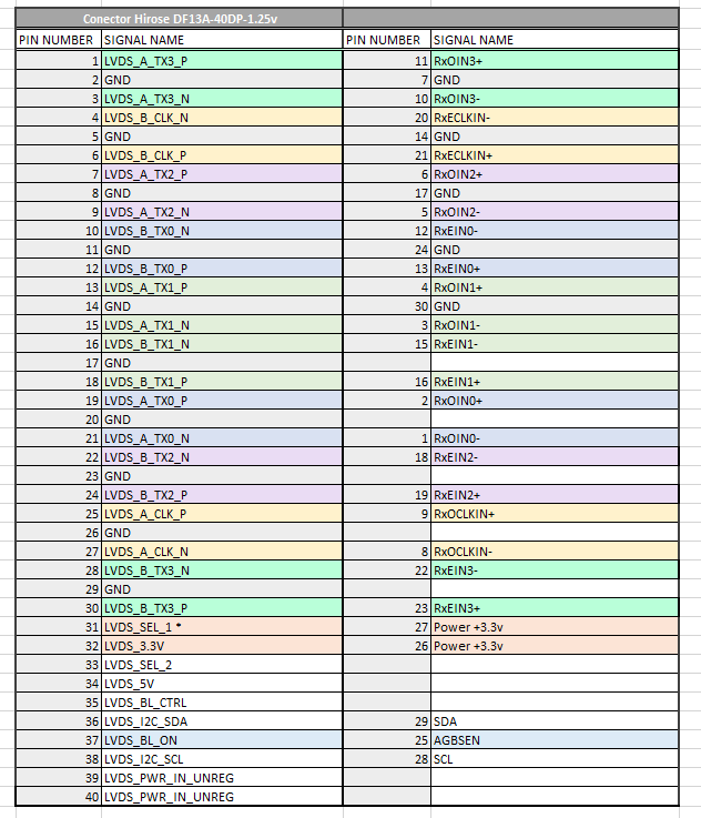
As I mentioned before, we are going to use the iMX8 together with the Iris as a carrier board, with its dedicated LVDS conector (X7). First, we need to know how to make the custom cable correctly, which is my main question.
After this, we need to know if any additional software configuration is required to display the image for that output.
Please, could you give me more guidance about this two topics?
I’m aware that iMX8 has a dedicated LVDS port. Seems there isn’t any adapter or board provided, so to make a custom cable for DF13A connector sounds easier than deal with that.
differential signals measured in the Iris Carrier board X7 connector don’t look properly.
There is no activity in clock lines, and the chanels only remain at 3,3v.
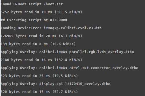
I know that it is necessary to change the device tree for our set up. But I was wonder if with the overlay configuration you provided in this link ( Device Tree Overlays (Linux) (toradex.com)) by defualt, about your 10.1 lvds capacitive touch display may show something.
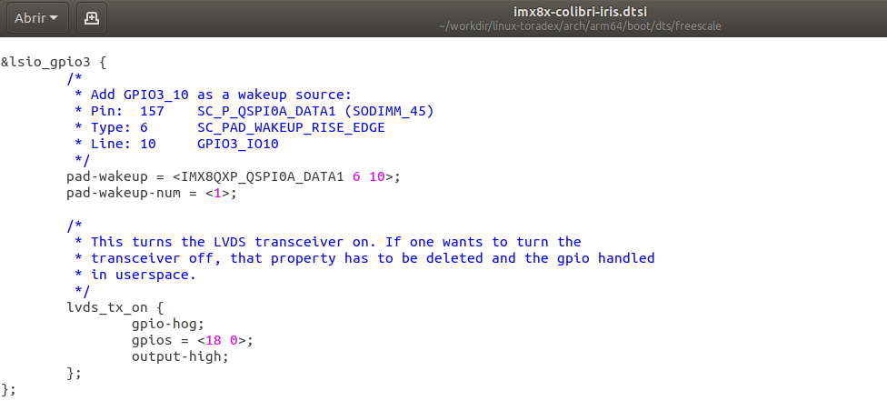
According to the diagrams of the Iris board, I understand that the connection that enables the integrated THC63LVD827 is the one corresponding to the SODIMM 99 line. However, in the comment (code above) it makes mention of the 45.
In the overlays I have dug a little and I also tested default display-dpi-lt170410_overlay.dtbo, and a modified one with another resolution parameters that have been tested by other means on our display panel.
Right now, we are again out of ideas, about what to do to get image on the screen through LVDS. Could you please give us more assistance in this regard?
According to the diagrams of the Iris board, I understand that the connection that enables the integrated THC63LVD827 is the one corresponding to the SODIMM 99 line. However, in the comment (code above) it makes mention of the 45.
You are right SODIMM uses Pin 99 for the LVDS Converter and the PIN45 is used for wakeup.
Right now, we are again out of ideas, about what to do to get image on the screen through LVDS. Could you please give us more assistance in this regard?
Could you share the dmesg log in a text file and output of fbset to see if the resolution is set correctly?