Goal
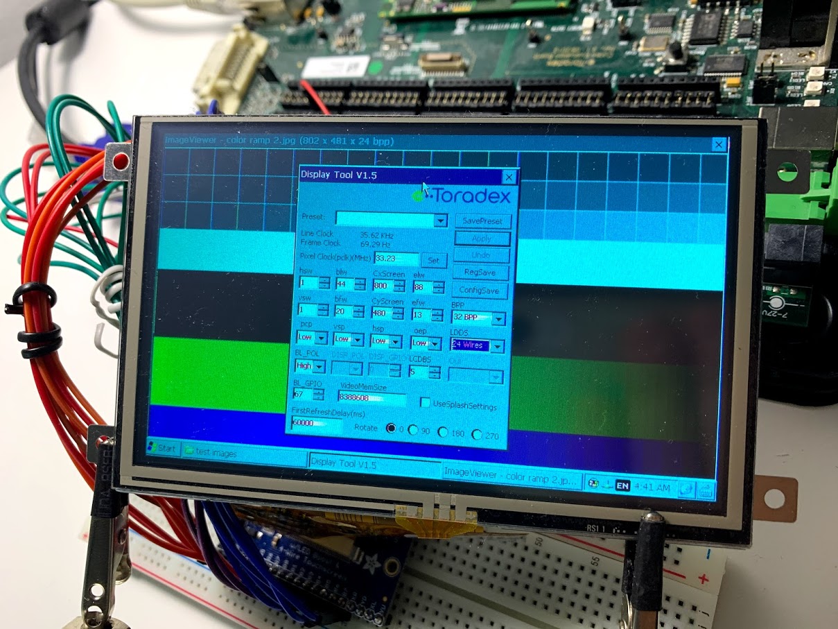
I need to drive my RGB TFT display in 24 bit interface mode on WinCE7 on the iMX7D. It looks like WinCE is not applying the 24 Wires mode when configured by DisplayTool. The colors are wrong, there is only green and blue - no reds (see Image 1).
Steps to reproduce
- Wire 24 bit display according to specification in the Colibri iMX7 datasheet, section 5.5 for 24 bit RGB interface and Colibri Eval Board Datasheet section 3.6.5 on the generic display connector.
- Configuration set for 24 Wires with DisplayTool 1.5
- Display comes up in general, but colors are all wrong (see Image 1).
- Change wiring for 18 bit rgb mode and keep settings the same.
- Now the colors are correct, even though 24 wire mode is set! Correct colors should only show, if wires are configured for 18 wires mode, because, according to specs, the modes aren’t compatible.
Further Observations
When wired for 24 bit mode and configured for 24 bit mode settings, check the LCD_DATA_18, 19, etc. lines using the GPIO tool. The pins are configured as input lines, when they really should be set to LCD_DATA_xx.
Conclusion
Somehow, the 24 bit rgb interface mode is not working.
Thanks for helping me out, your support is greatly appreciated 
[upload|IAiUcpXF9vqaSA+QrSVOQwm4aDA=]
[upload|48kVNQTl5y5ioMicRkI+NItV57U=]
[upload|GAKDjia4qFCtOyIyQlArZ8fCE9A=]
It looks like this related questions explains the same issue, but without a solution or fix:
Hi @MessagePump ,
This issue was fixed in 1.3b2, can you try to update and let me know if it helped?
Thanks Germano! In the meantime we decided to stick with the Colibri compatible 18 bit color interface - so I can’t confirm whether the update helps with 24 bit mode or not. I might not get to confirming the fix at all. Thanks for your fantastic support!
Hello @germano.tx,
optimistic about the fix I just checked WEC 7 1.3b2. There is progress - but the issue is not solved, yet. The red channel is completely missing - only green and blue are shown.
The color ramps should show red, green and blue. The reds remain completely black. Green and Blue appear ok. Please note the strange bright white areas in text input fields, e.g. in the BPP field.
I double checked my wiring, it’s according to the dev board and iMX7 data sheet.
Is there anything I can do on my end to get 24 bits to work?
Here is another update:
If I use the GPIO Tool to set SODIMM pins 136, 138, 140, 142, 144, 146 AltFn to lcdif.DATAxx - then the display colors are immediately shown correctly.
Dear @germano.tx is this something you can fix on your end?
Hi @MessagePump ,
Thanks for your feedback. It is indeed a BUG, the additional LCD lines are not configured!
I fixed that in the Bootloader. This will be released in the next official Beta (1.3b4), but you can test this version if you want:
https://share.toradex.com/mwerhye8g5az4z4
@germano.tx Wow - thanks for looking into this right away, even though it’s holiday season! I’ll get to checking the OS image next week and will send feedback.
Hi @germano.tx - I’m about to redo our image from scratch. In the release note for the IMX7 WIN CE 7 image V 1.3 there is no mention of this fix to the bootloader LCD line configuration. Is it included?
I redid the image using WEC7 V 1.3 and all worked fine out of the box. The issue seems completely solved - thank you.