Gpioset and reading registers with devmem2

I’m using gpioset to change gpio parameters, and it is working well, but I do not understand what I am seeing in registers.

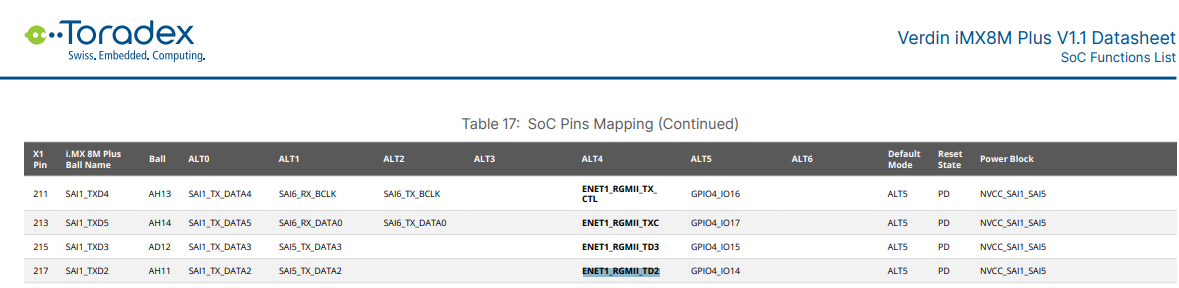
When I start from a freshly rebooted system, I see SODIMM_217 listed as an input.
This is GPIO4_IO14.

Consulting the reference manual, the register IOMUXC_SW_MUX_CTL_PAD_SAI1_TXD2 should be set to 0x05 for this to be a GPIO. However, when I read that register (mapped at 0x30330180 from the ref manual) using devmem2, it shows:

root@verdin-imx8mp-15446091:~# devmem2 0x30330180 w
/dev/mem opened.
Memory mapped at address 0x7f93dd1000.
Read at address  0x30330180 (0x7f93dd1180): 0x00000004

I don’t understand why that address is set to 0x4 (ALT4, or ENET1_RGMII_TD2 mode) instead of 5.

I’m pretty sure I’m using devmem2 properly, for if I change the direction of that gpio, I can see the GPIO4 Direction register (0x30230004) change…

# pin is an output due to a previous gpioset
root@verdin-imx8mp-15446091:~# devmem2 0x30230004 w
/dev/mem opened.
Memory mapped at address 0x7f8c383000.
Read at address  0x30230004 (0x7f8c383004): 0x30484000

# Now set back to input with gpioget
root@verdin-imx8mp-15446091:~# gpioget SODIMM_217

# GPIO4 direction register changed in memory!
root@verdin-imx8mp-15446091:~# devmem2 0x30230004 w
/dev/mem opened.
Memory mapped at address 0x7f8ab9f000.
Read at address  0x30230004 (0x7f8ab9f004): 0x30480000

# However, this pin is still reporting it is not a GPIO...
root@verdin-imx8mp-15446091:~# devmem2 0x30330180 w
/dev/mem opened.
Memory mapped at address 0x7f93dd1000.
Read at address  0x30330180 (0x7f93dd1180): 0x00000004

This behavior does not happen on other gpio pins - their MUX controllers are properly set to 5. What am I missing?

Hi, I’m the Toradex AI Assistant. The Toradex Support team will follow up with you shortly!

Did you like my answer?

:+1: :-1:


Hello!

The behavior you’re observing with the GPIO pin SODIMM_217 (GPIO4_IO14) is likely due to the System Controller Unit (SCU) and its firmware on the i.MX 8M Plus SoC. The SCU can override the default pin configurations set in the IOMUXC registers at boot time. This means that even though the reference manual indicates a reset state of 0x05 for GPIO mode, the SCU might be setting it to 0x04 (ENET1_RGMII_TD2 mode) as part of its default configuration.

To address this, you should verify the device tree configuration for your module. The device tree is responsible for defining the pin functions and should ensure that the pin is set to GPIO mode. Check the relevant device tree source files for any entries related to SODIMM_217 or GPIO4_IO14. Look for the fsl,pins property within the pin controller node, which specifies the pin’s function.

If the device tree does not explicitly set this pin to GPIO mode, you may need to modify it. You can add or adjust the device tree node to ensure the pin is configured correctly. This involves specifying the correct mux setting (0x05 for GPIO) in the device tree.

After making changes to the device tree, you’ll need to recompile it and deploy it to your module. This will ensure that the pin is configured as desired at boot time, overriding any default settings applied by the SCU.

This approach should resolve the discrepancy you’re seeing and allow the pin to function as a GPIO as expected. If you continue to experience issues, double-check the device tree settings and ensure that the correct configuration is being applied during the boot process.

Best regards, Toradex AI Assistant.

Please, also check if these links can help you solve your problem:

VF50 access to the registers.

By default, in most (if not all) of our images, SODIMM_217 is configured for the ENET1_RGMII_TD2 function (ALT4).

Using the gpioget/gpioset commands does not change the pin functionality. As a result, it does not function as a GPIO in your case (you can verify this using a voltmeter or an oscilloscope, as the pin will not change its level after using gpioset). To use it as a GPIO, you need to modify the device tree pinmuxing for that pin.

1 Like

OK, so this is a limitation of gpioset/gpioinfo, where that tool is not actually modifying all registers (specifically the MUX registers) directly. Good to know!

I am still learning how to understand device trees, but it seems like it I create an overlay dst file that adds the correct settings into the &iomuxc block, AND disable both &fecgrp and &fecsleepgrp, it should work… anything I am forgetting?

It’s not a limitation; it’s by design. The hardware configuration (including pin multiplexing) is defined in the Device Tree, and user-space tools must not alter it.

Basically, it’s correct. But you need to disable the &fec instead. Or you can choose another pin that is already configured as a GPIO.

It looks like I will have to use other GPIOs, as when I disable &fec and use the GPIOs, the board loses both network and HDMI (no idea if it is getting a kernel panic or what).

This is on a verdin imx8mp SoM using a Dahlia board and HDMI add on board. I am using Yocto (bitbake linux-toradex followed by bitbake tdx-reference-minimal-image). The rebuild process takes about 15 minutes, so any help you can provide that cuts down my iteration cycle is very much appreciated!

My overlay’s .dtsi file is as follows:

#include "imx8mp.dtsi"
#include "imx8mp-verdin.dtsi"

/ {
        compatible = "toradex,verdin-imx8mp-wifi-dev",
                        "toradex,verdin-dev",
                        "toradex,verdin-imx8mp",
                        "fsl,imx8mp";

        modem {
                compatible = "mycustom";   /*No kernel driver should claim this; we'll control from user-space */
                pinctrl-names = "default";
                pinctrl-0 = <&pinctrl_modem>;
                status = "okay";
        };
};

&fec {
        status = "disabled";
};

&iomuxc {
        pinctrl_modem: modemgrp {
                fsl,pins =
                        <MX8MP_IOMUXC_SAI1_TXD2__GPIO4_IO14             0x96>,  /* NEW: MODEM_CFG_0             OLD: SODIMM 217 */
                        <MX8MP_IOMUXC_SAI1_TXD3__GPIO4_IO15             0x96>,  /* NEW: MODEM_CFG_1             OLD: SODIMM 215 */
                        <MX8MP_IOMUXC_SAI1_TXD0__GPIO4_IO12             0x96>,  /* NEW: MODEM_CFG_2             OLD: SODIMM 221 */
                        <MX8MP_IOMUXC_SAI1_RXD5__GPIO4_IO07             0x96>,  /* NEW: MODEM_CFG_3             OLD: SODIMM 203 */
                        <MX8MP_IOMUXC_SAI1_TXD1__GPIO4_IO13             0x96>,  /* NEW: MODEM_CFG_4             OLD: SODIMM 219 */
                        <MX8MP_IOMUXC_SAI1_RXD6__GPIO4_IO08             0x96>,  /* NEW: MODEM_ON                OLD: SODIMM 205 */
                        <MX8MP_IOMUXC_SAI1_RXD7__GPIO4_IO09             0x1f6>, /* NEW: MODEM_AIRPLANE_N        OLD: SODIMM 207 */
                        <MX8MP_IOMUXC_SAI1_TXD4__GPIO4_IO16             0x96>,  /* NEW: MODEM_RESET_N           OLD: SODIMM 211 */
                        <MX8MP_IOMUXC_SAI1_TXD5__GPIO4_IO17             0x96>;  /* NEW: MODEM_DPR               OLD: SODIMM 213 */
                };
};

my custom layer’s bbappend file looks like this:

FILESEXTRAPATHS:prepend := "${THISDIR}/files:"

SRC_URI += "file://imx8mp-verdin-wifi-dev.dts"
SRC_URI += "file://mycustom-imx8mp-verdin.dtsi"

KERNEL_DEVICETREE += "freescale/imx8mp-verdin-wifi-dev.dtb"

# Destination for DTS and DTSI files
do_compile:prepend() {
    cp ${WORKDIR}/imx8mp-verdin-wifi-dev.dts ${S}/arch/arm64/boot/dts/freescale/ || echo "COULDN'T COPY 1"
    cp ${WORKDIR}/mycustom-imx8mp-verdin.dtsi ${S}/arch/arm64/boot/dts/freescale/ || echo "COULDN'T COPY 2"

@alex.tx -

I have successfully changed my device tree, adding a modem device that uses my modemctrl pintrl group, and disabling fec.

I have verified that &fec is disabled and that my modem is status=“okay” by looking at the file /sys/firmware/fdt.

The following is taken from /sys/firmware/fdt file on the device (after being converted with dtc):

modem {
                compatible = "mydev";
                pinctrl-names = "default";
                pinctrl-0 = <0xaa>;
                status = "okay";
        };

This is from the “pinctrl@30330000” block of the same file:

modemgrp {
                                        fsl,pins = <0x180 0x3e0 0x00 0x05 0x00 0x96 0x184 0x3e4 0x00 0x05 0x00 0x96 0x178 0x3d8 0x00 0x05 0x00 0x96 0x164 0x3c4 0x00 0x05 0x00 0x96 0x17c 0x3dc 0x00 0x05 0x00 0x96 0x168 0x3c8 0x00 0x05 0x00 0x96 0x16c 0x3cc 0x00 0x05 0x00 0x1f6 0x188 0x3e8 0x00 0x05 0x00 0x96 0x18c 0x3ec 0x00 0x05 0x00 0x96>;
                                        phandle = <0xaa>;
                                };

proof of disabled fec:

ethernet@30be0000 {
                                local-mac-address = [00 14 2d fb b0 4b];
                                compatible = "fsl,imx8mp-fec\0fsl,imx8mq-fec\0fsl,imx6sx-fec";
                                reg = <0x30be0000 0x10000>;
                                interrupts = <0x00 0x76 0x04 0x00 0x77 0x04 0x00 0x78 0x04 0x00 0x79 0x04>;
                                clocks = <0x02 0xc0 0x02 0xf2 0x02 0x84 0x02 0x83 0x02 0x85>;
                                clock-names = "ipg\0ahb\0ptp\0enet_clk_ref\0enet_out";
                                assigned-clocks = <0x02 0x5e 0x02 0x84 0x02 0x83 0x02 0x85>;
                                assigned-clock-parents = <0x02 0x36 0x02 0x3a 0x02 0x3b 0x02 0x39>;
                                assigned-clock-rates = <0x00 0x5f5e100 0x7735940 0x00>;
                                fsl,num-tx-queues = <0x03>;
                                fsl,num-rx-queues = <0x03>;
                                nvmem-cells = <0x5c>;
                                nvmem-cell-names = "mac-address";
                                fsl,stop-mode = <0x34 0x10 0x03>;
                                status = "disabled";
                                fsl,magic-packet;
                                phy-handle = <0x5d>;
                                phy-mode = "rgmii-id";
                                pinctrl-names = "default\0sleep";
                                pinctrl-0 = <0x5e>;
                                pinctrl-1 = <0x5f>;
                                phy-supply = <0x60>;
                                phandle = <0x100>;

However, on bootup, the registers are still set as though they are using the fecgrp!

root@verdin-imx8mp-15446091:~# devmem2 0x30330180 w
/dev/mem opened.
Memory mapped at address 0x7f949e7000.
Read at address  0x30330180 (0x7f949e7180): 0x00000004

That register is only set to 4 in the control group fecgrp, which is only used by fec… which is disabled!

Any thoughts on what is happening here? Thank you for your time!

(shared dts file obtained from the device’s /sys/firmware/fdt is here: Download - Toradex File Sharing Platform )

Could you please share the full source of your custom Device Tree (in mnemonics)?