GPIO configuration on IMX.6

Colibri iMX.6 512MB IT v1.1b
Colibri Evaluation Board
TorizonCore upstream 5.6.0

Hi,

Yesterday I managed (with a lot of help) to compile and run
Reading through the tutorial
Basic GPIO usage - Colibri Evaluation Board - Colibri iMX6 (toradex.com)

I managed through the parts to get gpioinfo to work:
##gpioinfo | grep -e “SODIMM” -e “MMX3”
gpiochip2 - 32 lines:
line 0: “SODIMM_111” unused input active-high
line 1: “SODIMM_113” unused input active-high
line 2: “SODIMM_115” unused input active-high
line 3: “SODIMM_117” unused input active-high
line 4: “SODIMM_119” unused input active-high
line 5: “SODIMM_121” unused input active-high
line 6: “SODIMM_123” unused input active-high
line 7: “SODIMM_125” unused input active-high
line 8: “SODIMM_110” unused input active-high
line 9: “SODIMM_112” unused input active-high
line 10: “SODIMM_114” unused input active-high

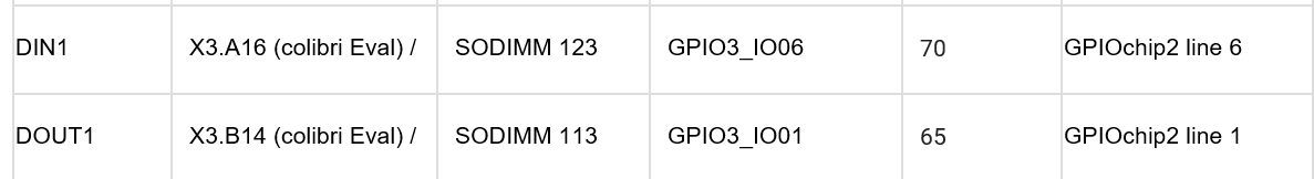
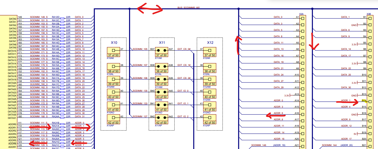
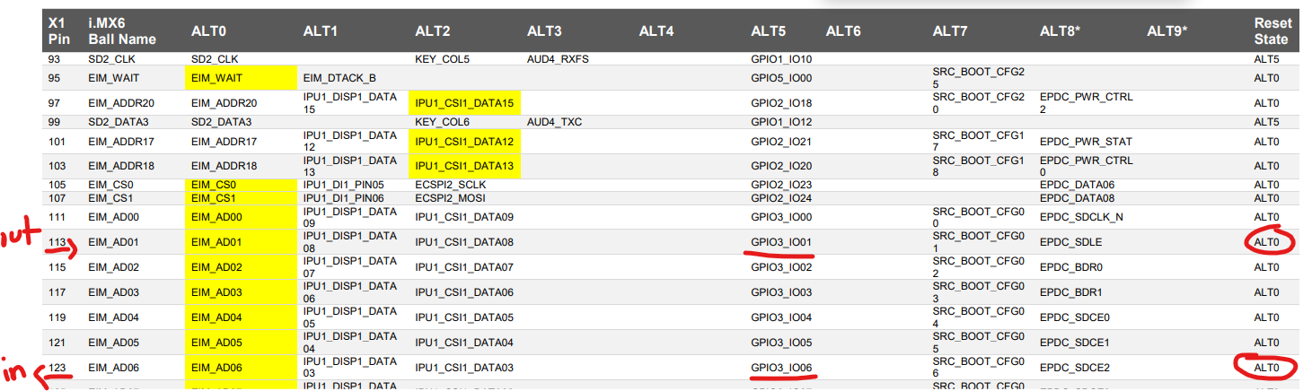
I need to configure SODIMM_113 as an output, but…

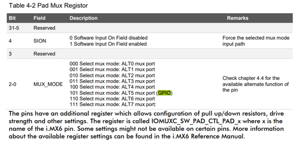
I don’t understand step 5 from the tutorial.
I am using TorizonCore, should I then install Linux and use the tool to configure my GPIOs as output?

Or can I just jump straight in to coding it with these examples lines:

  struct gpiod_chip *output_chip;    struct gpiod_line *output_line;

Configure a GPIO as output:

    /* open the GPIO bank */    
output_chip = gpiod_chip_open_by_number(bank);        
/* open the GPIO line */    
output_line = gpiod_chip_get_line(output_chip, line);    
/* config as output and set a description */  
  gpiod_line_request_output(output_line, "gpio-test",        GPIOD_LINE_ACTIVE_STATE_HIGH);

Toggle a GPIO:

    /* Clear */   
 int line_value = 0;    gpiod_line_set_value(output_line, line_value);     
   /* Set */   
 line_value = 1;    gpiod_line_set_value(output_line, line_value);

I see it was jus to add these lines:

struct gpiod_chip *output_chip;

    struct gpiod_line *output_line;

    /*configure a GPIO as an output - BANK: GPIOchip2, line 1*/

    output_chip = gpiod_chip_open_by_number(2);

    output_line = gpiod_chip_get_line(output_chip,1);

    gpiod_line_request_output(output_line, "gpio-test", GPIOD_LINE_ACTIVE_STATE_HIGH);

now I can see

root@a1d0bc27aea7:/# gpioinfo | grep -e "SODIMM" -e "MMX3"
        line   0: "SODIMM_111"       unused   input  active-high
        line   1: "SODIMM_113"  "gpio-test"  output  active-high [used]
        line   2: "SODIMM_115"       unused   input  active-high
        line   3: "SODIMM_117"       unused   input  active-high
        line   4: "SODIMM_119"       unused   input  active-high
        line   5: "SODIMM_121"       unused   input  active-high
        line   6: "SODIMM_123"       unused   input  active-high
        line   7: "SODIMM_125"       unused   input  active-high
        line   8: "SODIMM_110"       unused   input  active-high

Hi @leighjboyd ,

Just to be sure, did you already solve your issue? If I understood correctly it was setting a pin as output.

One thing to note is that the first link that you’ve posted is a GPIO guide for an older version of our Reference Image (BSP), which doesn’t necessarily apply to TorizonCore. I suggest reading How to Use GPIO on TorizonCore | Toradex Developer Center instead if using TorizonCore.

Let me know if you need any help.

Best regards,
Lucas Akira

No, its still not 100% working. Thanks for asking…

With the command line tools, I got this far:

my port mappings:

colibri-imx6-10866289:/sys/class/gpio# echo 1 > gpio65/value
colibri-imx6-10866289:/sys/class/gpio# cat gpio65/direction
out
colibri-imx6-10866289:/sys/class/gpio# cat gpio65/value
1
colibri-imx6-10866289:/sys/class/gpio# echo 0 > gpio65/value
colibri-imx6-10866289:/sys/class/gpio# cat gpio65/value
0
colibri-imx6-10866289:/sys/class/gpio#

but I don’t see the output toggling.

from the c program, I’m using:


#include <stdio.h>
#include <unistd.h>
#include <gpiod.h>
#include <string.h>

int ToggleGPIO(int argc, char *argv[])
{
	int line_value = 0;
	char chip[32];
	unsigned int offset;
	int input;
        

    snprintf(chip, sizeof(chip), "gpiochip2");

    while (1) {
        sleep(1);

        printf("Setting pin to %d\n", line_value);
        offset = 1;
        line_value = !line_value;
        gpiod_ctxless_set_value(chip, offset,line_value, false,"gpio-toggle",NULL,NULL);
        //gpiod_ctxless_set_value("gpiochip2", offset,line_value, false,"gpio-toggle",NULL,NULL);

        offset = 6;
        input = gpiod_ctxless_get_value(chip, offset, false, "DIN1");
        printf("Input: %d\n", input);
     }

with output:

Setting pin to 0
Input: -1
Setting pin to 1
Input: -1

In any case, I can’t seem to see the IO toggling on the actual board.
I am using the voltmeter and the LED connected to X3.B14

I don’t know if the output is pull-up/pull-down or what…

Update:
A little more information…
Today I used the CLI and successfully turned on/off gpio50 via the CLI using
echo 0 > gpio50/value
echo 1 > gpio50/value

but it doesn’t work still with gpio65…

Another update:
re-wrote my code to cycle through all banks 0 to 7 and all offsets 0 to 32 and checked for toggling outputs on connectors X22, X3 and X9. I found that the following work:

X22.4 .6 .7 .8 .9 .17 .21 .22
X3.A7 .A12 .A20 .A24 .A32
X3.B10 .B12 .B20 .B23 .B24
X3.C11 .C12 .C20 .C23 .C31 .C32
X9 SODIMM 71. 82. 68. 48. 62. 46. 80. 72. 78, 58. 60, 104, 102

The rest don’t toggle.

Now to check if there is anything in common with these outputs…

Still no luck.
Tried it again with a different module, and a different Colibri Evaluation Carrier Board, to be sure.
Still no response from my DOUT1 pin, which should be X3.B14 if I am reading this correctly.

And these pins are set up with reset mode as ALT0

However, I think that my device tree sets these up as ALT5
this is from the file Imx6dl.dtsi which includes imx6dl-pinfunc.h.

According to the following, MUX mode for ALT5 (GPIO) should be 0b101 = 0x5
image

Anyways, to verify that these are set up as GPIO, I thought I could do a
docker run --rm -it --device /dev/gpiochip2 torizonextras/arm32v7-gpiod

and then check gpioinfo (i added some notes to the right):

root@d6e4b1b96bff:/# gpioinfo
gpiochip2 - 32 lines:
        line   0: "SODIMM_111"       unused   input  active-high
        line   1: "SODIMM_113"       unused  output  active-high - doesn't work (want as input anyway)
        line   2: "SODIMM_115"       unused  output  active-high
        line   3: "SODIMM_117"       unused  output  active-high
        line   4: "SODIMM_119"       unused  output  active-high
        line   5: "SODIMM_121"       unused  output  active-high
        line   6: "SODIMM_123"       unused  output  active-high - **doesn't work
        line   7: "SODIMM_125"       unused  output  active-high
        line   8: "SODIMM_110"       unused  output  active-high
        line   9: "SODIMM_112"       unused  output  active-high
        line  10: "SODIMM_114"       unused  output  active-high
        line  11: "SODIMM_116"       unused  output  active-high
        line  12: "SODIMM_118"       unused  output  active-high
        line  13: "SODIMM_120"       unused  output  active-high
        line  14: "SODIMM_122"       unused  output  active-high
        line  15: "SODIMM_124"       unused  output  active-high
        line  16:      unnamed       unused  output  active-high
        line  17:  "SODIMM_96"       unused  output  active-high
        line  18:  "SODIMM_77"       unused  output  active-high
        line  19:  "SODIMM_25"       unused  output  active-high - doesn't work          
        line  20:  "SODIMM_27"       unused  output  active-high - doesn't work     
        line  21:  "SODIMM_88"       unused  output  active-high
        line  22:  "SODIMM_90"       unused  output  active-high
        line  23:  "SODIMM_31"       unused  output  active-high - doesn't work
        line  24:  "SODIMM_23"       unused  output  active-high - doesn't work
        line  25:  "SODIMM_29"       unused  output  active-high - doesn't work
        line  26:  "SODIMM_71"       unused  output  active-high - works
        line  27:  "SODIMM_73"       unused  output  active-high
        line  28:  "SODIMM_92"       unused  output  active-high
        line  29:  "SODIMM_81"       unused  output  active-high - works
        line  30: "SODIMM_131"       unused  output  active-high  - works

** = the outputs I’m interested in.

Does this means that device tree is correct?

Here’s my code, which should toggle all outputs every second

int line_value = 0;
char chip[32];
int bank;
unsigned int offset;

while (1) {

        sleep(1);
        line_value = !line_value;

        for (bank = 0; bank <8; bank++){
            snprintf(chip, sizeof(chip), "gpiochip%d",bank);
            printf("Setting %s to %d\n",chip, line_value);

            for (offset =1; offset <31; offset++){
                    //printf("Setting %s line %d to %d\n",chip, offset, line_value);
                    gpiod_ctxless_set_value(chip, offset, line_value, false,"gpio-toggle",NULL,NULL);
            }
       }
}

What am I missing?
Maybe its configured as pull up (the LED I hooked it up to is always on) and it should be pull down? (if so, where do i configure that one?)

Thanks
Leigh

Hi @leighjboyd ,

So you really need SODIMM 113 and 123 specifically as GPIOs.
After discussing your issue internally we suspect that the problem is in the device tree: it seems that these two pins are already being used for something else, so they’re not really available as GPIOs, even if gpioinfo says otherwise.

I’ll need to run some tests to see if this is the case. If so, the device tree has to be updated, in which case I’ll detail what needs to be done.

Best regards,
Lucas Akira

Sorry to interject here, but my co-workers and I have had problems with the device tree. It is difficult to understand what pins are assigned to what function – and the only reliable way to get some things to work is to slog through the source files of the device tree. That can involve tracing multiple files through the kernel sources and separate device tree overlay Git repositories (and then wondering if those were the actual sources for the dtb’s in your distributions!). OR… decompile the supplied dtb(s).

Where are the precedence rules defined for multiple device tree includes in a flattened tree, and overlays.txt file and the order of files within?

In our case the problem is with a 24-bit wide display and the fact that some of the display pins beyond 16-bit display use are assigned to other functions in the supplied device tree(s) files.

The device tree thing is fast becoming overly complex and utterly confusing IMO. As usual, it was a simple concept that has now seemingly been taken to extremes.

Thanks Lucas,

We were arriving at the same conclusion. I’m not a device tree expert but a colleague took a look at it briefly and said that it looks like these outputs are being configured in imx6dl-pinfunc.h.

once here, on line 502 as an address line ALT0 (0x0), and again on line 505 as a GPIO, ALT5 (0x5):


image

same story here where the pin at 0x1b4 is defined as an address line AD06 with ALT0 functionality and as a GPIO3_IO06 with ALT5 functionality.
image

later, in imx6qdl-colibri.dtsi, this #define gets used to configure:

    pinctrl_weim_sram: weimsramgrp {
        fsl,pins = <
            MX6QDL_PAD_EIM_OE__EIM_OE_B     0xb0b1
            MX6QDL_PAD_EIM_RW__EIM_RW       0xb0b1
            /* Data */
            MX6QDL_PAD_CSI0_DATA_EN__EIM_DATA00 0x1b0b0
            MX6QDL_PAD_CSI0_VSYNC__EIM_DATA01   0x1b0b0
.
.
             /* Address */
.
.
            MX6QDL_PAD_EIM_DA7__EIM_AD07        0xb0b1
            MX6QDL_PAD_EIM_DA6__EIM_AD06        0xb0b1
            MX6QDL_PAD_EIM_DA5__EIM_AD05        0xb0b1
            MX6QDL_PAD_EIM_DA4__EIM_AD04        0xb0b1
            MX6QDL_PAD_EIM_DA3__EIM_AD03        0xb0b1
            MX6QDL_PAD_EIM_DA2__EIM_AD02        0xb0b1
            MX6QDL_PAD_EIM_DA1__EIM_AD01        0xb0b1
            MX6QDL_PAD_EIM_DA0__EIM_AD00        0xb0b1

I have yet to find where GPIOs are configured… but I guess this will be a matter of adding the GPIO3_IO06 and GPIO3_IO01 to a list somewhere?

perhaps here in imx6dl.dtsi?

&gpio3 {
    gpio-ranges = <&iomuxc  0 97  2>, <&iomuxc 2 105 8>, <&iomuxc 10 99 6>,
              <&iomuxc 16 81 16>;
};

Just guessing around in the dark…

Also, in include/dt-bindings/gpio/gpio.h I found these definitions.

#ifndef _DT_BINDINGS_GPIO_GPIO_H
#define _DT_BINDINGS_GPIO_GPIO_H
/* Bit 0 express polarity */
#define GPIO_ACTIVE_HIGH 0
#define GPIO_ACTIVE_LOW 1

/* Bit 1 express single-endedness */
#define GPIO_PUSH_PULL 0
#define GPIO_SINGLE_ENDED 2

/* Bit 2 express Open drain or open source */
#define GPIO_LINE_OPEN_SOURCE 0
#define GPIO_LINE_OPEN_DRAIN 4

/*
* Open Drain/Collector is the combination of single-ended open drain interface.
* Open Source/Emitter is the combination of single-ended open source interface.
*/

#define GPIO_OPEN_DRAIN (GPIO_SINGLE_ENDED | GPIO_LINE_OPEN_DRAIN)
#define GPIO_OPEN_SOURCE (GPIO_SINGLE_ENDED | GPIO_LINE_OPEN_SOURCE)

/* Bit 3 express GPIO suspend/resume and reset persistence */
#define GPIO_PERSISTENT 0
#define GPIO_TRANSITORY 8

/* Bit 4 express pull up */
#define GPIO_PULL_UP 16

/* Bit 5 express pull down */
#define GPIO_PULL_DOWN 32
#endif

but I don’t see them being used, but I’m thinking if one were to use them , then the gpio-ranges should look something like this?

&gpio3 {
    gpio-ranges = <&iomuxc  0 97  GPIO_OPEN_SOURCE>, <&iomuxc 2 105 GPIO_TRANSITORY>, <&iomuxc 10 99 GPIO_OPEN_DRAIN>,
              <&iomuxc 16 81 GPIO_PULL_UP>;
};

still don’t know what the other numbers mean yet…

Hi,

I tried to make these modifications to : /home/leighjboyd/tcbworkdir/device-trees/dts-arm32/imx6qdl-colibri.dtsi:

pinctrl_weim_sram: weimsramgrp {
    fsl,pins = <
        MX6QDL_PAD_EIM_OE__EIM_OE_B     0xb0b1
        MX6QDL_PAD_EIM_RW__EIM_RW       0xb0b1
        /* Data */
        MX6QDL_PAD_CSI0_DATA_EN__EIM_DATA00 0x1b0b0
        MX6QDL_PAD_CSI0_VSYNC__EIM_DATA01   0x1b0b0
        MX6QDL_PAD_CSI0_DAT4__EIM_DATA02    0x1b0b0
        MX6QDL_PAD_EIM_DA10__EIM_AD10       0xb0b1
        MX6QDL_PAD_EIM_DA9__EIM_AD09        0xb0b1
        MX6QDL_PAD_EIM_DA8__EIM_AD08        0xb0b1
        MX6QDL_PAD_EIM_DA7__EIM_AD07        0xb0b1
        /*MX6QDL_PAD_EIM_DA6__EIM_AD06      0xb0b1*/
        MX6QDL_PAD_EIM_DA5__EIM_AD05        0xb0b1
        MX6QDL_PAD_EIM_DA4__EIM_AD04        0xb0b1
        MX6QDL_PAD_EIM_DA3__EIM_AD03        0xb0b1
        MX6QDL_PAD_EIM_DA2__EIM_AD02        0xb0b1
        /*MX6QDL_PAD_EIM_DA1__EIM_AD01      0xb0b1*/
        MX6QDL_PAD_EIM_DA0__EIM_AD00        0xb0b1
    >;
};

and rebuild with the torizoncore-build build I get the error message:

Updating TorizonCore image in place.
Removing output directory ‘torizon-core-docker-colibri-imx6-Tezi_5.6-CAN_SPI_GPIO_overlay’ due to build errors
Error: Currently it is not possible to customize the containers of a base image already containing container images

I’m not sure what that means… Does it mean that the evaluation image:
local: torizon-core-docker-evaluation-colibri-imx6-Tezi_5.6.0-devel-202202+build.21.container.tar
is not allowed to be modified by anything other than an overlay?

I would like to keep this evaluation image, since it has portainer and such, but maybe its time I need to abandon it now? I don’t really use Portainer much anyways…

Leigh

Just chiming in here. Unfortunately I don’t have a Eval board in my home office, I have an Aster but it doesn’t route SODIMM 113 to anywhere measurable on the board.

But, I was able to do an equivalent test. So as you seem to have noticed SODIMM 113 is not enabled as a GPIO by default in the device tree and is in use by the weim interface. In general you’d need to disable any interface that uses a pin that you want to repurpose.

As a test/example I re-configured SODIMM 194 as a GPIO, by default this pin is used in I2C. Starting off here’s the changes I did in the device tree:

diff --git a/dts-arm32/imx6dl-colibri-eval-v3.dts b/dts-arm32/imx6dl-colibri-eval-v3.dts
index 64cacf0..50df0c7 100644
--- a/dts-arm32/imx6dl-colibri-eval-v3.dts
+++ b/dts-arm32/imx6dl-colibri-eval-v3.dts
@@ -129,7 +129,7 @@
  * Colibri I2C: I2C3_SDA/SCL on SODIMM 194/196 (e.g. RTC on carrier board)
  */
 &i2c3 {
-       status = "okay";
+       status = "disabled";
 
        /* M41T0M6 real time clock on carrier board */
        rtc_i2c: rtc@68 {
 
diff --git a/dts-arm32/imx6qdl-colibri.dtsi b/dts-arm32/imx6qdl-colibri.dtsi
index 803a6e1..0389f12 100644
--- a/dts-arm32/imx6qdl-colibri.dtsi
+++ b/dts-arm32/imx6qdl-colibri.dtsi
@@ -1130,6 +1130,9 @@
                        MX6QDL_PAD_DISP0_DAT19__GPIO5_IO13      0x1b0b0
                        MX6QDL_PAD_DISP0_DAT18__GPIO5_IO12      0x1b0b0
                        MX6QDL_PAD_NANDF_D1__GPIO2_IO01         0x1b0b0
+                        MX6QDL_PAD_GPIO_6__GPIO1_IO06           0x1b0b0
                >;
        };

To explain what I did above:

  • First I disabled i2c3 as this interface uses SODIMM 194 by default
  • Then I reconfigured the pin as a GPIO and added it to a pin group. In this case i added it to the existing pin group pinctrl_weim_gpio_1. Since this pin group isn’t being used by anything it gets exported to user-space, which is ideal for a GPIO

With that, I applied this customized device tree and I was able to use SODIMM 194 as a GPIO and it seems to work as expected. With that said, I would expect a similar process is needed for SODIMM 113 in your case. Though I’ll see if I can have someone else who has a evaluation board available to check since I was unable to test this pin directly myself.

I’m not sure what that means… Does it mean that the evaluation image:
local: torizon-core-docker-evaluation-colibri-imx6-Tezi_5.6.0-devel-202202+build.21.container.tar
is not allowed to be modified by anything other than an overlay?

That error message just means you’re trying to bundle containers in an image that already has pre-bundled containers. The evaluation containers in this case (i.e. portainer).

Best Regards,
Jeremias

Hi @mmccullotn ,

Although your situation seems to be similar, I don’t think it’s exactly related to this one.

If you have a specific question regarding that could you please create another topic?

Best regards,
Lucas Akira

Hi @leighjboyd ,

I have some good news for you: based on the steps given by @jeremias.tx I was able to make both SODIMM 113 and 123 function correctly as GPIO. I made some tests using gpioset and your ToggleGPIO() and everything works: both pins can be set and I can read the correct value of SODIMM 123.

Here is what I’ve done in the device tree:

  • Disabled weim as that uses the pins we need;
  • Created a custom pinctrl group with both pins in it set as GPIO;
  • In iomuxc I added this group to pinctrl-0, a property that wasn’t declared before;
  • I also created pinctrl-names inside iomuxc.

All these changes are in the attached Device Tree source file. It is a copy of imx6dl-colibri-eval-v3.dts albeit with the above modifications. You can use TorizonCore Builder to create a custom image that uses this .dts file.

Let me know if that works for you.

Best regards,
Lucas Akira

imx6dl-colibri-eval-v3-gpio-custom.dts (4.5 KB)

You are awesome!!

Thank you very much.

I will likely not have time to test it until Thursday

Leigh

Yes!

That did the trick.

Thank-you sooooo much. Toradex support rules!

1 Like