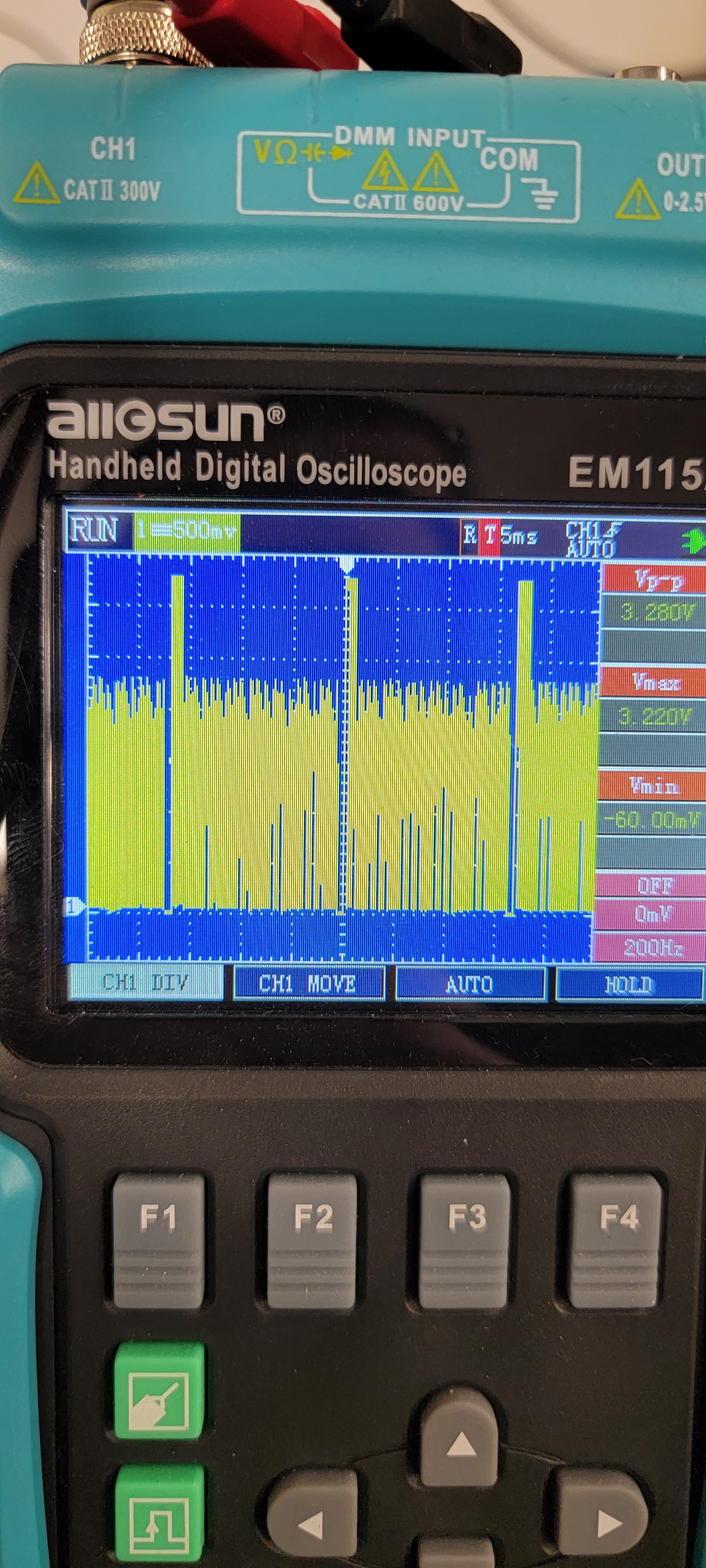
I setup a GPIO pin through userspace acording to this tutorial: GPIO Tutorial, but regardless of wether I set it to 1 or 0 I get a weird a weird but consistent pulse on pin 64 which is GPI05_IO09 linux# 137. Please see photo.
This is on a custom carrier board of ours. I’m not sure where the problem may lie, just looking for some troubleshooting tips.
Greetings @SterlingArcher,
First of all what version of our software are you running here?
Secondly, I assume the issue is that by default SODIMM pin 64 is not configured as a GPIO by default in the software. By default it’s used as one of the data lines for the parallel RGB display interface. This might explain why you’re seeing activity, just not the activity you expected.
You would need to configure the software (Device tree) to change this pin’s function from a display data line to a GPIO. However mind you this means the display interface would not be functional, if that is something you also need.
Best Regards,
Jeremias
I’m using the reference multimedia image found here.
I’m not sure what I was thinking, I thought that pin 64 was in the GPIO tutorial. I’ve been occupied with a lot of stuff. You’re right I need to mod the dev tree.
I disabled the IPU that was using the pins but I’m assuming that this isn’t enough, and the GPIO pins I want to use need to be configured as generic GPIOs according to this thread.
The only thing is that your colleague alex.tx suggested a way to do it but my device tree looks a bit different. He said to modify the gpio I want similarly to pinctrl_gpio1 to pinctrl_gpio7 in his device tree example:
&iomuxc {
	pinctrl-names = "default";
	pinctrl-0 = <&pinctrl_gpio1 &pinctrl_gpio2 &pinctrl_gpio3
		&pinctrl_gpio4 &pinctrl_gpio6 &pinctrl_gpio7>;
};
But I have something more like this:
iomuxc@20e0000 {

                compatible = "fsl,imx6dl-iomuxc";

                reg = <0x20e0000 0x4000>;

                pinctrl-names = "default";

                //pinctrl-0 = <0x2d 0x2e 0x2f 0x30 0x31 0x32 0x33 0x34 0x35 0x36 0x37>;

                pinctrl-0 = <0x34 0x35 0x36 0x37>;

                phandle = <0x1f>;

                imx6qdl-colibri {

                    // csi_gpio-1 {

                    //  fsl,pins = <0x2f8 0x6e0 0x00 0x05 0x00 0x1b0b0 0x27c 0x664 0x00 0x05 0x00 0x1b0b0 0x14c 0x51c 0x00 0x05 0x00 0x1b0b0 0x11c 0x4ec 0x00 0x05 0x00 0x1b0b0 0x178 0x548 0x00 0x05 0x00 0x130b0 0x12c 0x4fc 0x00 0x05 0x00 0x1b0b0 0x120 0x4f0 0x00 0x05 0x00 0x1b0b0 0x114 0x4e4 0x00 0x05 0x00 0x1b0b0 0x118 0x4e8 0x00 0x05 0x00 0x1b0b0 0x1d0 0x5a0 0x00 0x05 0x00 0x1b0b0 0x148 0x518 0x00 0x05 0x00 0x1b0b0 0x2fc 0x6e4 0x00 0x05 0x00 0x1b0b0>;

                    //  phandle = <0x33>;

                    // };

                    csi_gpio-2 {

                        fsl,pins = <0x130 0x500 0x00 0x05 0x00 0x1b0b0>;

                        phandle = <0xb6>;

                    };

                    gpio-1 {

                        fsl,pins = <0x170 0x540 0x00 0x05 0x00 0x1b0b0 0x29c 0x684 0x00 0x05 0x00 0x1b0b0 0x290 0x678 0x00 0x05 0x00 0x1b0b0 0x1f0 0x5c0 0x00 0x05 0x00 0x1b0b0 0xac 0x3c0 0x00 0x05 0x00 0x1b0b0 0x34c 0x734 0x00 0x05 0x00 0x1b0b0 0x294 0x67c 0x00 0x05 0x00 0x1b0b0 0x340 0x728 0x00 0x05 0x00 0x1b0b0>;

                        phandle = <0x34>;

                    };

                    gpio-2 {

                        fsl,pins = <0x238 0x608 0x00 0x05 0x00 0x1b0b0 0x23c 0x60c 0x00 0x05 0x00 0x1b0b0>;

                        phandle = <0x35>;

                    };
Maybe the difference is he may be doing a device tree overlay whereas I’m editing the device tree directly, but either way I’m not sure exactly where I need to specify the GPIOs I want to use. Any advice would be appretiated.
Thank you,
Luc
The device tree you provided, where did you get this from? With the hexadecimal values this doesn’t look like the device tree from the source. Seems like it’s a partially processed/compiled device tree output.
Anyways as you can see the source device tree here: imx6qdl-colibri.dtsi « dts « boot « arm « arch - linux-toradex.git - Linux kernel for Apalis, Colibri and Verdin modules
Should be easier to interpret and modify.
Best Regards,
Jeremias
This device tree I decompiled into a .dts and then modified what I needed, then recompiled it into a .dtb into the boot folder. Got this right off of the multimedia reference image that you guys provide.
Thank you, the one I had was a bit confusing. The device tree you just gave me, can I just compile that into a .dtb and replace into the boot folder, or should I make it a device tree overlay?
One of the pins I’m trying to mux as a regular gpio is GPIO5_IO09 which is MX6QDL_PAD_DISP0_DAT15__IPU1_DISP0_DATA15, third from the bottom of the list of pins below.
pinctrl_ipu1_lcdif: ipu1lcdifgrp {
		fsl,pins = <
			MX6QDL_PAD_DI0_DISP_CLK__IPU1_DI0_DISP_CLK	0xa1
			MX6QDL_PAD_DI0_PIN15__IPU1_DI0_PIN15		0xa1
			MX6QDL_PAD_DI0_PIN2__IPU1_DI0_PIN02		0xa1
			MX6QDL_PAD_DI0_PIN3__IPU1_DI0_PIN03		0xa1
			MX6QDL_PAD_DISP0_DAT0__IPU1_DISP0_DATA00	0xa1
			MX6QDL_PAD_DISP0_DAT1__IPU1_DISP0_DATA01	0xa1
			MX6QDL_PAD_DISP0_DAT2__IPU1_DISP0_DATA02	0xa1
			MX6QDL_PAD_DISP0_DAT3__IPU1_DISP0_DATA03	0xa1
			MX6QDL_PAD_DISP0_DAT4__IPU1_DISP0_DATA04	0xa1
			MX6QDL_PAD_DISP0_DAT5__IPU1_DISP0_DATA05	0xa1
			MX6QDL_PAD_DISP0_DAT6__IPU1_DISP0_DATA06	0xa1
			MX6QDL_PAD_DISP0_DAT7__IPU1_DISP0_DATA07	0xa1
			MX6QDL_PAD_DISP0_DAT8__IPU1_DISP0_DATA08	0xa1
			MX6QDL_PAD_DISP0_DAT9__IPU1_DISP0_DATA09	0xa1
			MX6QDL_PAD_DISP0_DAT10__IPU1_DISP0_DATA10	0xa1
			MX6QDL_PAD_DISP0_DAT11__IPU1_DISP0_DATA11	0xa1
			MX6QDL_PAD_DISP0_DAT12__IPU1_DISP0_DATA12	0xa1
			MX6QDL_PAD_DISP0_DAT13__IPU1_DISP0_DATA13	0xa1
			MX6QDL_PAD_DISP0_DAT14__IPU1_DISP0_DATA14	0xa1
			MX6QDL_PAD_DISP0_DAT15__IPU1_DISP0_DATA15	0xa1
			MX6QDL_PAD_DISP0_DAT16__IPU1_DISP0_DATA16	0xa1
			MX6QDL_PAD_DISP0_DAT17__IPU1_DISP0_DATA17	0xa1
		>;
This is initially tied to IPU, but would I just remove it from the list of pins that the IPU uses, and put it under gpio-1 for example? I put what I was thinking between some stars ***.
pinctrl_gpio_1: gpio-1 {
		fsl,pins = <
			MX6QDL_PAD_EIM_D27__GPIO3_IO27      0x1b0b0
			MX6QDL_PAD_NANDF_D6__GPIO2_IO06     0x1b0b0
			MX6QDL_PAD_NANDF_D3__GPIO2_IO03     0x1b0b0
			MX6QDL_PAD_ENET_REF_CLK__GPIO1_IO23 0x1b0b0
			MX6QDL_PAD_DI0_PIN4__GPIO4_IO20     0x1b0b0
			MX6QDL_PAD_SD4_DAT3__GPIO2_IO11     0x1b0b0
			MX6QDL_PAD_NANDF_D4__GPIO2_IO04     0x1b0b0
			MX6QDL_PAD_SD4_DAT0__GPIO2_IO08     0x1b0b0
                   ***MX6QDL_PAD_DISP0_DAT15__IPU1_DISP0_DATA15	0x1b0b0 ***
		>;
The device tree you just gave me, can I just compile that into a .dtb and replace into the boot folder, or should I make it a device tree overlay?
Either full compiling or device tree overlay would be fine. The effort for either method is comparable in my opinion. So it mostly comes down to preference. Also yes you can just replace the active *.dtb on the device. As long as your changes don’t also require a recompilation of the kernel. Which it shouldn’t for your case since you’re just changing some pins.
As for modifying the device tree, you don’t actually need to remove the pin from pinctrl_ipu1_lcdif. You just need to make sure that whatever interface is using pinctrl_ipu1_lcdif, is not enabled. Which in this case is the lcd node. I believe we enable lcd by default via device tree overlays on the system. Anyways as long as multiple interfaces aren’t trying to use the same pin at the same time.
Best Regards,
Jeremias
Thanks a lot, that solved my issue. I put the pins back where they were in iomux and ensured that the IPU was disabled.
Glad I was able to be of assistance!