Hello @khaled.hassan,
This is how I did basic CAN interface testing when I only had to validate, that my device tree works. I hope it helps you with your issue. I do not have any other CAN nodes and I do not currently posses oscilloscope, so it is just a very basic testing.
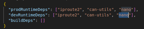
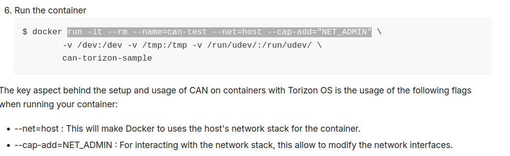
First I created a docker image using How to Use CAN on Torizon OS, Make sure to run following command to enable ARM emulation before building can-torizon-sample:
$ docker run --rm -it --privileged torizon/binfmt
Then move the docker archive to Verdin module and start it. Once you are in docker environment, my testing started to differ.
Physically connecting RX and TX signals on the same CAN interface (shorting) will not work, because the CAN node cannot acknowledge itself. You would need to connect two different CAN interfaces (which is actually possible on Verdin, but I have not used it).
For first testing I used SW loop-back. I ran candump in background creating canout.txt, while sending data with cansend. Messages appeared in canout.txt, but I am not sure why it always appeared twice.
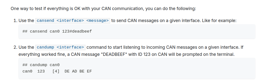
Commands:
# ip link set can0 type can bitrate 250000 loopback on
# ip link set can0 up
# candump can0 > canout.txt &
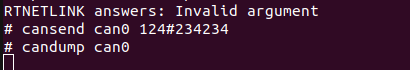
# cansend can0 300#AA.BB.CC.11
# cansend can0 300#AA.BB.CC.22
# cansend can0 300#AA.BB.CC.33
# ip link set can0 down
# cat canout.txt
Content of canout.txt:
  can0  300   [4]  AA BB CC 11
  can0  300   [4]  AA BB CC 11
  can0  300   [4]  AA BB CC 22
  can0  300   [4]  AA BB CC 22
  can0  300   [4]  AA BB CC 33
  can0  300   [4]  AA BB CC 33
In the second test I actually measured voltage difference behind CAN transceiver, which translates TX to CAN High and CAN Low. It is important to understand, how transceiver works, nicely explained here.
When sending CAN command via cansend, the command is repeated in a loop until acknowledged. Due to this behavior, you can do a basic check even without another node. Command will never be acknowledged and will be repeated in an infinite loop. You can take advantage of this by measuring “average voltage” between CAN_H and CAN_L with a simple voltmeter.
There is a simple rule that the more bits have high value, the lower the voltage difference will be. Be aware that the voltage difference will not increase or decrease with ideal consistency, because CAN protocol data link layer contains other bits that you cannot set directly, for example CRC. But you can do at least basic checks. Just for illustration, here are some measurement which I did at my custom carrier board.
cansend can0 7FF#FF.FF.FF.FF -> 0.53V
cansend can0 0FF#FF.FF.FF.FF -> 0.61V
cansend can0 F0F#FF.FF.FF.FF -> 0.62V
cansend can0 F00#FF.FF.FF.FF -> 0.71V
cansend can0 0F0#FF.FF.FF.FF -> 0.72V
cansend can0 00F#FF.FF.FF.FF -> 0.76V
cansend can0 001#FF.FF.00.00 -> 1.15V
cansend can0 001#00.00.FF.FF -> 1.15V
cansend can0 7FF#00.00.00.00 -> 1.30V
cansend can0 002#00.00.00.00 -> 1.41V
cansend can0 001#00.00.00.00 -> 1.46V
To do this measurements yourself, make sure to disable SW loopback, and then make sure to change state to down and back up after each command.
# ip link set can0 type can bitrate 250000 loopback off
# ip link set can0 up
# cansend can0 7FF#FF.FF.FF.FF
# ip link set can0 down
# ip link set can0 up
# cansend can0 0FF#FF.FF.FF.FF
# ip link set can0 down
# ip link set can0 up
...
I hope this helps you or others testing CAN. It does not test the receiving side, but this will only be possible with a real second node.
Best Regards,
Jaroslav