Apalis i.MX6 GPIO control

Hello,

I am trying to set up some GPIOs for usage for sending and reading information.
Since I’m new to Torizon first I decided to start with getting the example code from Toradex git running.

I changes some of the printing functions to use C++ libraries. This is the code I use:

#include <iostream>
#include <cstring>
#include <gpiod.h>
#include <unistd.h>

struct gpiod_line* get_gpio_line(char* bank, int gpio) {
    struct gpiod_chip* chip;
    struct gpiod_line* line;

    // open the GPIO bank
    chip = gpiod_chip_open_by_name(bank);
    if (chip == nullptr) {
        return nullptr;
    }

    // open the GPIO line
    line = gpiod_chip_get_line(chip, gpio);
    if (line == nullptr) {
        return nullptr;
    }

    return line;
}

int main(int argc, char* argv[]) {
    struct gpiod_line* output_line;
    struct gpiod_line* input_line;
    struct gpiod_line_event event;
    int line_value = 0;
    int ret;
    char chip[32];
    unsigned int offset;

    // check the arguments
    std::cout << "1" << std::endl;
    if (!(argc == 3 || argc == 5)) {
        std::cout << "Usage by bank/pin number:\n"
            "gpio-event INPUT-BANK-NUMBER INPUT-GPIO-NUMBER OUTPUT-BANK-NUMBER OUTPUT-GPIO-NUMBER\n"
            "Usage by SODIMM name:\n"
            "gpio-event INPUT-SODIMM-NAME OUTPUT-SODIMM-NAME\n";
        return EXIT_FAILURE;
    }
    

    if (argc == 5) {
        std::cout << "2" << std::endl;
        char gpio_chip[10];
        snprintf(gpio_chip, sizeof(gpio_chip), "gpiochip%s", argv[1]);
        input_line = get_gpio_line(gpio_chip, atoi(argv[2]));
        snprintf(gpio_chip, sizeof(gpio_chip), "gpiochip%s", argv[3]);
        output_line = get_gpio_line(gpio_chip, atoi(argv[4]));

    }
    else {
        if (gpiod_ctxless_find_line(argv[1], chip, sizeof(chip), &offset) <= 0) {
            std::cout << "Error finding GPIO" << std::endl;
            return EXIT_FAILURE;
        }
        std::cout << "3" << std::endl;
        input_line = get_gpio_line(chip, offset);
        if (input_line == nullptr) {
            std::cout << "Error setting gpiod" << std::endl;
            return EXIT_FAILURE;
        }
        std::cout << "4" << std::endl;

        if (gpiod_ctxless_find_line(argv[2], chip, sizeof(chip), &offset) <= 0) {
            std::cout << "Error finding GPIO" << std::endl;
            return EXIT_FAILURE;
        }
        std::cout << "4" << std::endl;
        output_line = get_gpio_line(chip, offset);
        if (output_line == nullptr) {
            std::cout << "Error setting gpiod" << std::endl;
            return EXIT_FAILURE;
        }
        std::cout << "5" << std::endl;
    }

    ret = gpiod_line_request_rising_edge_events(input_line, "gpio-test");
    if (ret < 0) {
        std::cout << "Request events failed" << std::endl;
        return EXIT_FAILURE;
    }
    std::cout << "6" << std::endl;

    ret = gpiod_line_request_output(output_line, "gpio-test",
        GPIOD_LINE_ACTIVE_STATE_HIGH);
    if (ret < 0) {
        std::cout << "Request output failed" << std::endl;
        return EXIT_FAILURE;
    }
    std::cout << "7" << std::endl;

    while (true) {
        gpiod_line_event_wait(input_line, nullptr);

        if (gpiod_line_event_read(input_line, &event) != 0)
            continue;
        std::cout << "8" << std::endl;
        // this should always be a rising event
        if (event.event_type != GPIOD_LINE_EVENT_RISING_EDGE)
            continue;
        std::cout << "9" << std::endl;
        // toggle output
        line_value = !line_value;
        std::cout << "Setting pin to " << line_value << std::endl;
        gpiod_line_set_value(output_line, line_value);
        std::cout << "10" << std::endl;
	} 
    std::cout << "11" << std::endl;
	return EXIT_SUCCESS;
}

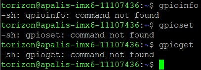
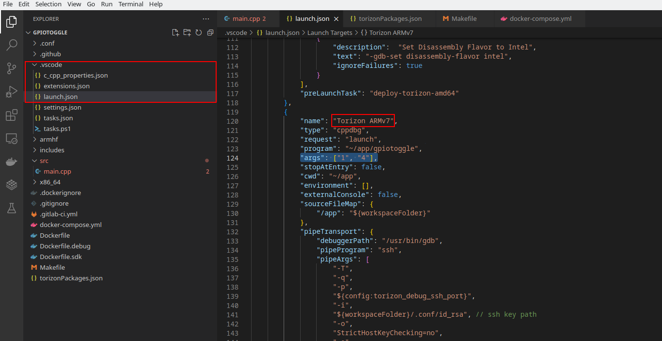
But when I run it I get the following error:

Usage by bank/pin number:
gpio-event INPUT-BANK-NUMBER INPUT-GPIO-NUMBER OUTPUT-BANK-NUMBER OUTPUT-GPIO-NUMBER
Usage by SODIMM name:
gpio-event INPUT-SODIMM-NAME OUTPUT-SODIMM-NAME
[Inferior 1 (process 37) exited with code 01]

I am not sure what am I doing wrong as I am fairly new to Torizon and Docker.
I ried following the tutorial on GPIO usage and adding the following line to the Dockerfile:

docker run --rm -it --init --device /dev/gpiochip1 yourdockerhubuser/arm32v7-c-gpiod
like this at the bottom:

# ARG CROSS_SDK_BASE_TAG=2.7-bullseye
ARG CROSS_SDK_BASE_TAG=3.0.2-20230323-bookworm
ARG BASE_VERSION=2.5-bullseye

##
# Board architecture
# arm or arm64
##
ARG IMAGE_ARCH=armhf

##
# Application Name
##
ARG APP_EXECUTABLE=pesho


# BUILD ------------------------------------------------------------------------
FROM torizon/debian-cross-toolchain-${IMAGE_ARCH}:${CROSS_SDK_BASE_TAG} As Build

ARG IMAGE_ARCH
ARG COMPILER_ARCH
ENV IMAGE_ARCH ${IMAGE_ARCH}

# __deps__
RUN apt-get -q -y update && \
    apt-get -q -y install libcurl4-gnutls-dev:armhf \
    apt-get -q -y install \
# DOES NOT REMOVE THIS LABEL: this is used for VS Code automation
    # __torizon_packages_dev_start__
    # __torizon_packages_dev_end__
# DOES NOT REMOVE THIS LABEL: this is used for VS Code automation
    libgpiod-dev:armhf \
    libgpiod2:armhf \
    libpthread-stubs0-dev:armhf \
    && \
    apt-get clean && apt-get autoremove && \
    rm -rf /var/lib/apt/lists/*
# __deps__

COPY . /app
WORKDIR /app

# RUN echo  arm-linux-gnueabihf-g++  --version

RUN if [ "$IMAGE_ARCH" = "arm64" ] ; then \
        make ARCH=. CC=aarch64-linux-gnu-g++ ; \
    elif [ "$IMAGE_ARCH" = "arm" ] ; then \
        make ARCH=. CC=arm-linux-gnueabihf-g++ ; \
    elif [ "$IMAGE_ARCH" = "amd64" ] ; then \
        make ARCH=. CC=x86_64-linux-gnu-g++ ; \
    fi

# BUILD ------------------------------------------------------------------------


# DEPLOY ------------------------------------------------------------------------
FROM --platform=linux/${IMAGE_ARCH} torizonextras/debian:${BASE_VERSION} AS Deploy

ARG IMAGE_ARCH
ARG APP_EXECUTABLE
ENV APP_EXECUTABLE ${APP_EXECUTABLE}

RUN apt-get -y update && apt-get install -y --no-install-recommends \
# DOES NOT REMOVE THIS LABEL: this is used for VS Code automation
    # __torizon_packages_prod_start__
    # __torizon_packages_prod_end__
# DOES NOT REMOVE THIS LABEL: this is used for VS Code automation
	&& apt-get clean && apt-get autoremove && rm -rf /var/lib/apt/lists/*

# Allow the user torizon use GPIOs
RUN usermod -a -G gpio torizon

# copy the build
COPY --from=Build /app/bin /app


# ADD YOUR ARGUMENTS HERE
CMD [ "./app/pesho", "--rm", "-it",  "--init",  "--device",  "/dev/gpiochip1", "yourdockerhubuser/arm32v7-c-gpiod"]
#CMD [ "./app/pesho", "--rm", "-it",  "--init",  "--device",  "/dev/gpiochip1", "pesho/arm32v7-c-gpiod"]
# DEPLOY ------------------------------------------------------------------------

As it can be seen I also include the libgpiod-dev:armhf \ libgpiod2:armhf \
and
RUN usermod -a -G gpio torizon.

The Makefile has the following configurations:

# tool macros
CC := g++
CCFLAGS := -Iincludes/ -I/usr/include/x86_64-linux-gnu 
DBGFLAGS := -g
LDFLAGS := -lcurl -lgpiod -lpthread
CCOBJFLAGS := $(CCFLAGS) -c
ARCH :=

# path macros
BIN_PATH := $(ARCH)/bin
OBJ_PATH := $(ARCH)/obj
SRC_PATH := src
DBG_PATH := $(ARCH)/debug

# compile macros
TARGET_NAME := pesho
TARGET := $(BIN_PATH)/$(TARGET_NAME)
TARGET_DEBUG := $(DBG_PATH)/$(TARGET_NAME)

# src files & obj files
SRC := $(foreach x, $(SRC_PATH), $(wildcard $(addprefix $(x)/*,.c*)))
OBJ := $(addprefix $(OBJ_PATH)/, $(addsuffix .o, $(notdir $(basename $(SRC)))))
OBJ_DEBUG := $(addprefix $(DBG_PATH)/, $(addsuffix .o, $(notdir $(basename $(SRC)))))

# clean files list
DISTCLEAN_LIST := $(OBJ) \
					$(OBJ_DEBUG)

CLEAN_LIST := $(TARGET) \
				$(TARGET_DEBUG) \
				$(DISTCLEAN_LIST)

# default rule
default: makedir all

# non-phony targets
$(TARGET): $(OBJ)
	$(CC) $(CCFLAGS) -o $@ $(OBJ) $(LDFLAGS)

$(OBJ_PATH)/%.o: $(SRC_PATH)/%.c*
	$(CC) $(CCOBJFLAGS) -o $@ $<

$(DBG_PATH)/%.o: $(SRC_PATH)/%.c*
	$(CC) $(CCOBJFLAGS) $(DBGFLAGS) -o $@ $<

$(TARGET_DEBUG): $(OBJ_DEBUG)
	$(CC) $(CCFLAGS) $(DBGFLAGS) $(OBJ_DEBUG) -o $@ $(LDFLAGS)

# phony rules
.PHONY: makedir
makedir:
	@mkdir -p $(BIN_PATH) $(OBJ_PATH) $(DBG_PATH)

.PHONY: all
all: $(TARGET)

.PHONY: debug
debug: $(TARGET_DEBUG)

.PHONY: clean
clean:
	@echo CLEAN $(CLEAN_LIST)
	@rm -f $(CLEAN_LIST)

.PHONY: distclean
distclean:
	@echo CLEAN $(CLEAN_LIST)
	@rm -f $(DISTCLEAN_LIST)

Is desired GPI accessibly by the GPIO command line tool?

If you mean the commands I can use like gpioinfo, gpiodetect and so on I can’t use them in the terminal. Should I enter something else to use them?

When I do the command ls /dev/gpiochip* I get the following:

/dev/gpiochip0 /dev/gpiochip2 /dev/gpiochip4 /dev/gpiochip6
/dev/gpiochip1 /dev/gpiochip3 /dev/gpiochip5

Is that what you mean or something else?

#gpioinfo
#gpioset
#gpioget

As I said, if I call them from the terminal I can’t use them.

But do you mean by calling them from the terminal in the docker or just the Torizon Core?
Because I’ve been trying from the TorizonCore

What does it mean? Could you provide an output when you try to run that commands?

image

Hi @Svetoslav ,

The message you’re getting is expected: the example code you’re using is gpio-event.c (not gpio-toggle.c that you linked). This code toggles an output pin whenever the input pin changes from 0 V to 3.3V. Both pins must be defined by arguments you pass to the program before running it.

In the following part of your dockerfile:

# ADD YOUR ARGUMENTS HERE
CMD [ "./app/pesho", "--rm", "-it",  "--init",  "--device",  "/dev/gpiochip1", "yourdockerhubuser/arm32v7-c-gpiod"]
#CMD [ "./app/pesho", "--rm", "-it",  "--init",  "--device",  "/dev/gpiochip1", "pesho/arm32v7-c-gpiod"]

You’re getting things mixed up: you’re passing docker run arguments as arguments for your program.
In this case CMD should have 4 arguments after the binary name: the first two referring to the input pin, and the other two related to the output pin.

For instance, if you want to use gpiochip1, pin 5 as an input pin and gpiochip1, pin 4 as an output pin, CMD should be like this:

CMD [ "./app/pesho", "1", "5",  "1" , "4"]

The above method is only valid for the release container. If you want to have the arguments when debugging you have to add them in .vscode/launch.json. The corresponding architecture for your SoM (ARMv7 for iMX6 modules) has to be modified to be similar to this:

[...]
            "name": "Torizon ARMv7",
            "type": "cppdbg",
            "request": "launch",
            "program": "~/app/cppNewGPIOexample",
            "args": ["1","5", "1", "4"],
            "stopAtEntry": false,
            "cwd": "~/app",
            "environment": [],
            "externalConsole": false,
            "sourceFileMap": {
                "/app": "${workspaceFolder}"
            },
[...]

The docker run arguments should instead be passed to your project as an equivalent entry in docker-compose.yml. As an example, if you want to have access to gpiochip1 (equivalent of --device /dev/gpiochip1 in docker run), you have to add the devices section in docker-compose.yml, similar to this:

version: "3.9"
services:
  cpp-new-gpio-example-debug:
    build:
      context: .
      dockerfile: Dockerfile.debug
    image: ${LOCAL_REGISTRY}:5002/cpp-new-gpio-example-debug:${TAG}
    ports:
      - 2230:2230
    devices:
      - "/dev/gpiochip1:/dev/gpiochip1"

  cpp-new-gpio-example:
    build:
      context: .
      dockerfile: Dockerfile
    devices:
      - "/dev/gpiochip1:/dev/gpiochip1"
    image: ${DOCKER_LOGIN}/cpp-new-gpio-example:${TAG}

As a final note, I’d recommend first trying to run gpio-toggle.c (torizon-samples/gpio-toggle.c at bullseye · toradex/torizon-samples · GitHub), which only requires two arguments referring to one GPIO pin. It is easier to understand and test compared to gpio-event.c.

See if this makes things clearer.

Best regards,
Lucas Akira

Thank you for the given information.
Currently using the code for gpio-toggle:

#include <iostream>
#include <unistd.h>
#include <gpiod.h>
#include <string.h>

int main(int argc, char *argv[]) {
    int line_value = 0;
    char chip[32];
    unsigned int offset;

    /* check the arguments */
    if (argc == 2) {
        /* get SODIMM parameters */
        if (gpiod_ctxless_find_line(argv[1], chip, sizeof(chip), &offset) <= 0) {
            std::cout << "Error finding GPIO" << std::endl;
            return EXIT_FAILURE;
        }
    } else if (argc == 3) {
        snprintf(chip, sizeof(chip), "gpiochip%s", argv[1]);
        offset = atoi(argv[2]);
    } else {
        std::cout << "Usage by bank/pin number:" << std::endl
                  << "\tgpio-toggle OUTPUT-BANK-NUMBER OUTPUT-GPIO-NUMBER" << std::endl
                  << "Usage by SODIMM name:" << std::endl
                  << "\tgpio-toggle OUTPUT-SODIMM-NAME" << std::endl;
        return EXIT_FAILURE;
    }

    while (true) {
        line_value = !line_value;
        gpiod_ctxless_set_value(chip, offset, line_value, false, "gpio-toggle", NULL, NULL);
        sleep(1);
        std::cout << "Setting pin to " << line_value << std::endl;
    }

    return EXIT_SUCCESS;
}

And added the following lines to the docker-compose as you advised:

version: "3.9"
services:
  pesho_debeliq-debug:
    build:
      context: .
      dockerfile: Dockerfile.debug
    image: ${LOCAL_REGISTRY}:5002/pesho_debeliq-debug:${TAG}
    ports:
      - 2230:2230
    volumes:
      - /sys:/sys
      - type: bind
        source: /media
        target: /media
    devices:
      - "/dev/gpiochip1:/dev/gpiochip1"

  pesho_debeliq:
    build:
      context: .
      dockerfile: Dockerfile
    image: ${DOCKER_LOGIN}/pesho_debeliq:${TAG}
    volumes:
      - /sys:/sys
      - type: bind
        source: /media
        target: /media
    devices:
      - "/dev/gpiochip1:/dev/gpiochip1"

but still enters the else state when I run this code:

Usage by bank/pin number:
	gpio-toggle OUTPUT-BANK-NUMBER OUTPUT-GPIO-NUMBER
Usage by SODIMM name:
	gpio-toggle OUTPUT-SODIMM-NAME
[Inferior 1 (process 38) exited with code 01]

I don’t really know what the arfc is and what I should get and if this is what I’m suppose to get.

Hi @Svetoslav ,

Right, you added /dev/gpiochip1 in docker-compose.yml correctly. The message you’re receiving:

Usage by bank/pin number:
	gpio-toggle OUTPUT-BANK-NUMBER OUTPUT-GPIO-NUMBER
Usage by SODIMM name:
	gpio-toggle OUTPUT-SODIMM-NAME
[Inferior 1 (process 38) exited with code 01]

means that the code is being compiled correctly as well, so you also added libgpiod-dev:armhf as it should be.

The gpio-toggle.c example changes the state of a GPIO pin from 0V to 3.3V and from 3.3V to 0V each 1 second, so if you put an LED to the pin you should see it blinking with a 1 second period.

The only thing that needs to be done is to tell the program which GPIO pin you want to use. To do this you pass arguments when starting the program. If you don’t pass any arguments, or pass the wrong number of them it prints the message above and ends.

You need to pass two arguments, both being integer numbers:

  • The first one being the GPIO bank
  • The second one being the GPIO pin inside the bank

To better understand how to get the numbers above, I’ve done a detailed example that uses some pins available in a Ixora carrier board, see below for more details:


GPIO Example

Suppose that you want to use GPIO2, pin 4. If you look at the Apalis iMX6 datasheet, you can see that it corresponds to Pin 1 of the SoM:

Looking at the Ixora V1.1/V1.2 datasheet you can see that Pin 1 of the Apalis is connected to a pin in the extension header (X27) present in the Ixora carrier board (highlighted in red):

Let’s also mark a GND pin (highlighted in black) in case we need to use it.

The exact location of the mentioned pins in the Ixora is highlighted below:

You can use these pins to verify if our program is actually working.

Inside Linux GPIO banks start being numbered in zero, so GPIO2 pin 4 in the datasheet actually corresponds to GPIO1 pin 4 in our program. If you added /dev/gpiochip1 in your docker-compose.yml you should be good to go.


With the example in mind, the arguments you need to pass to the program should be 1 and 4, being the GPIO bank and pin, respectively. To pass them during debug open .vscode/launch.json present in your project directory, look for Torizon ARMv7, then add the arguments in the args section:

If you want to pass the arguments in a release build of your project see my previous reply where I show how to do this.

After doing all of that see if the program executes correctly and if the GPIO pin is actually changing.

Hope this helps.

Best regards,
Lucas Akira

1 Like

Thank you @lucas_a.tx for your support, that helped and I managed to get both the GPIO tuggle and GPIO event working.

I only have one more question. If I want to make both of them working together how do I need to add the arguments in lauch.json? Also if I want to make more than 1 GPIO pin working together.

I tried by adding just another line of args[“1”, “5”] for example but I am not sure if this is how it’s done for more than one GPIO being set.
Because also when I do this “args”: [“1”,“5”, “1”, “4”] it gives me an error that GPIO is not detected.

And for the activation on event how do I combine a GPIO output with innput pins there? Or this is how it should be done then? “args”: [“1”,“5”, “1”, “4”].

Hi @Svetoslav ,

Thank you @lucas_a.tx for your support, that helped and I managed to get both the GPIO tuggle and GPIO event working.

Glad I was able to help!

I only have one more question. If I want to make both of them working together how do I need to add the arguments in lauch.json? Also if I want to make more than 1 GPIO pin working together.

I tried by adding just another line of args[“1”, “5”] for example but I am not sure if this is how it’s done for more than one GPIO being set.

If you need to use more than two arguments you just add them to the same args array e.g. ["1", "5", "1", "4"]. I don’t think that creating more than one args array will work.

Because also when I do this “args”: [“1”,“5”, “1”, “4”] it gives me an error that GPIO is not detected.
And for the activation on event how do I combine a GPIO output with innput pins there? Or this is how it should be done then? “args”: [“1”,“5”, “1”, “4”].

It looks like this problem is related to how your code is using the arguments.

How are you planning on combining the GPIO toggle code with the event code? With three GPIO pins? What is your objective?

The way the arguments are interpreted is up to the code itself, that is, your implementation of it.

For example, our GPIO event code uses four arguments to get 2 GPIO pins in this way:

  • GPIO Input bank
  • GPIO Input pin
  • GPIO Output bank
  • GPIO Output pin

Best regards,
Lucas Akira

Hello again @lucas_a.tx,

I am trying now to implement all the GPIOs some as inputs some as outputs but as I mentioned, putting the pins in that way [“1”,“5”, “1”, “4”]. Basically if I put more than one pin it doesn’t work.

I discovered that if I have put for example [“1”,“5”], I can still call pin 4 that is on GPIO1 in the following way: gpiod_ctxless_set_value(chip, offset, line_value, false, “gpio-toggle”, NULL, NULL) where I just change offset to be the number that I want. I understand that this is not correct but I do not know in what other way to do that.
I currently need to use GPIO1 and 3 for outputs and GPIO5,6,7,8 as inputs.
I am trying to read the information from the pins with gpiod_ctxless_get_value_multiple and gpiod_ctxless_get_value.
How do I need to initialize and add the other GPIOs in order to be able to use all of them?

Currently I have the following code:

int main(int argc, char *argv[]) {
    int line_value = 0;
    char chip[32];
    unsigned int offset;

    /* check the arguments */
    if (argc == 2) {
        /* get SODIMM parameters */
        if (gpiod_ctxless_find_line(argv[1], chip, sizeof(chip), &offset) <= 0) {
            std::cout << "Error finding GPIO" << std::endl;
            return EXIT_FAILURE;
        }
    } 
    else if (argc == 3) {
        snprintf(chip, sizeof(chip), "gpiochip%s", argv[1]);
        offset = atoi(argv[2]);
    } 
    else {
        std::cout << "Usage by bank/pin number:" << std::endl
                  << "\tgpio-toggle OUTPUT-BANK-NUMBER OUTPUT-GPIO-NUMBER" << std::endl
                  << "Usage by SODIMM name:" << std::endl
                  << "\tgpio-toggle OUTPUT-SODIMM-NAME" << std::endl;
        return EXIT_FAILURE;
    }
    serial_init(chip, offset);
    while(true){
        serial_read();
        sleep(5);
    }
    return 0;
}
void serial_init(char chip[], unsigned int offset){
    unsigned int reset_pin = 4; //1
    unsigned int cs_pin = 6; //1

    //Reset the ADC at start
    gpio_set(chip, reset_pin, 0);
    std::this_thread::sleep_for(std::chrono::nanoseconds(100));
    gpio_set(chip, reset_pin, 1);
    std::this_thread::sleep_for(std::chrono::nanoseconds(100));

    //Set reset to 0 and cs to 1
    gpio_set(chip,reset_pin, 0);
    gpio_set(chip, cs_pin, 1);

    //initialize SCLK
    // pwm_init(); // Export chip to be used by the docker
    pwm_set(PERIOD, DUTY_CYCLE); //set perdiod and duty cycle to pwm0
    std::cout << "Successful initialization of PWM" << std::endl;
    // while(true){}
}

void serial_read(){
    char chip_1[32] = "gpiochip1";
    char chip_0[32] = "gpiochip0";
    char chip_5[32] = "gpiochip5";

    unsigned int cs_pin = 6;        //gpiochip1
    unsigned int dout[2] = {2, 6};  //gpiochip0
    unsigned int firstdata = 10;    //gpiochip5
    unsigned int busy = 9;          //gpiochip5

    int dout_data[100];

 
    int val = gpiod_ctxless_get_value(chip_1, cs_pin, false, "gpio-toggle");
    if(val < 0){
        std::cout << "failed to read gpio\n";
        std::exit(EXIT_FAILURE);    
    }
    // gpio_get_value_two_pins(chip_0, dout, dout_data);
    std::cout << "data" << val << std::endl;
}
void gpio_set(char chip[], unsigned int offset, int line_value) {
    if(gpiod_ctxless_set_value(chip, offset, line_value, false, "gpio-toggle", NULL, NULL) < 0){
        std::cout << "failed to set pin " << offset << " to " << line_value << std::endl;
        std::exit(EXIT_FAILURE);    
    }
    std::cout << "Setting pin to " << line_value << std::endl;
}


void gpio_get_value_two_pins(char chip[], unsigned int offsets[], int *values){
    if(gpiod_ctxless_get_value_multiple(chip, offsets, values, 2, false, "gpio-toggle") < 0){
        std::cout << "failed to read DOUTA and DOUTB\n";
        std::exit(EXIT_FAILURE);    
    }
}

I understand that chip gives the value gpiochip and the number that is given in lauch.json so 1 in that case. And the offset is the second number for example 5. If I change the offset to 4 I can work with that pin also but if I change the chip I cannot work with the other pins.
I am not sure how to initialize when it’s more than one gpio and how to do that and how to access the variables the proper way if I want to work with more than one pin.

Hi @Svetoslav ,

I am trying now to implement all the GPIOs some as inputs some as outputs but as I mentioned, putting the pins in that way [“1”,“5”, “1”, “4”]. Basically if I put more than one pin it doesn’t work.

That’s because the sample code you are using wasn’t made to receive four or more arguments. You can see this in the if statement at the beginning of your code:

int main (int argc, char *argv[]) {
  [...]
  if (argc == 2) {
  [...]
  } else if (argc == 3) {
  [...]
  } else {
  [...]
  }
}

argc gets the number of arguments passed by your program plus one. That’s valid for any C/C++ code, not just for our extension.

For instance, if your args array is:

[“1”,“5”, “1”, “4”]

The value of argc will be 5. In your current code this will lead you to the else statement, which prints the error message you are seeing:

        std::cout << "Usage by bank/pin number:" << std::endl
                  << "\tgpio-toggle OUTPUT-BANK-NUMBER OUTPUT-GPIO-NUMBER" << std::endl
                  << "Usage by SODIMM name:" << std::endl
                  << "\tgpio-toggle OUTPUT-SODIMM-NAME" << std::endl;
        return EXIT_FAILURE;

I recommend you take a look at this link for more details regarding argc:
c++ - What does int argc, char *argv[] mean? - Stack Overflow


I discovered that if I have put for example [“1”,“5”], I can still call pin 4 that is on GPIO1 in the following way: gpiod_ctxless_set_value(chip, offset, line_value, false, “gpio-toggle”, NULL, NULL) where I just change offset to be the number that I want. I understand that this is not correct but I do not know in what other way to do that.

If you have the GPIO bank added in devices you have access to all pins in it. Keep in mind that using arguments to get the offsets is just an implementation we did for our example, it doesn’t mean that you have to do it exactly like that. You can set offset directly if you’re not planning to change it afterwards.

I understand that chip gives the value gpiochip and the number that is given in lauch.json so 1 in that case. And the offset is the second number for example 5. If I change the offset to 4 I can work with that pin also but if I change the chip I cannot work with the other pins.
I am not sure how to initialize when it’s more than one gpio and how to do that and how to access the variables the proper way if I want to work with more than one pin.

Well, your questions are more related to code implementation. You can use arguments to get the GPIO bank and offsets, or just put the bank/offset numbers directly, it really depends on your use case.

Our code is a simple example used to introduce GPIO usage with TorizonCore. While I can give you some general directions on how to expand upon it, how you implement it is ultimately up to you, the developer.

For specific questions about the gpiod functions you can go to the libgpiod documentation:
https://libgpiod.readthedocs.io/en/latest/index.html

Best regards,
Lucas Akira

Thank you for clearing this up for me.

But I feel that the problem might still be at the GPIOs because I tried declaring all the pins and modified the code to read all the arguments but still only the ones in bank 1 were activated.

Then I tried with the code that I provided earlier declaring only one pin from bank 0 like that [“0” , “2”] and tried reading from this pin and after that also writing but both weren’t successful. While keeping the same configurations I tried writing and reading pins from bank 1 and it was successful.
Same happened when I declared a pin from bank 5. I cannot read or write on it but I can read or write on pins on bank 1 which aren’t even declared.

I thought that old docker image might still be used and that it takes configurations from there so I deleted the docker image and compiled the code again but that didn’t change anything.

Hi @Svetoslav ,

But I feel that the problem might still be at the GPIOs because I tried declaring all the pins and modified the code to read all the arguments but still only the ones in bank 1 were activated.

Then I tried with the code that I provided earlier declaring only one pin from bank 0 like that [“0” , “2”] and tried reading from this pin and after that also writing but both weren’t successful. While keeping the same configurations I tried writing and reading pins from bank 1 and it was successful.
Same happened when I declared a pin from bank 5. I cannot read or write on it but I can read or write on pins on bank 1 which aren’t even declared.

If you intend to use other GPIO banks you need to add them to the devices section in the docker-compose.yml file the same way you did it before. If you want to use banks 0 and 1 for instance your docker-compose.yml should be similar to this:

version: "3.9"
services:
  pesho_debeliq-debug:
    build:
      context: .
      dockerfile: Dockerfile.debug
    image: ${LOCAL_REGISTRY}:5002/pesho_debeliq-debug:${TAG}
    ports:
      - 2230:2230
    volumes:
      - /sys:/sys
      - type: bind
        source: /media
        target: /media
    devices:
      - "/dev/gpiochip0:/dev/gpiochip0"
      - "/dev/gpiochip1:/dev/gpiochip1"

  pesho_debeliq:
    build:
      context: .
      dockerfile: Dockerfile
    image: ${DOCKER_LOGIN}/pesho_debeliq:${TAG}
    volumes:
      - /sys:/sys
      - type: bind
        source: /media
        target: /media
    devices:
      - "/dev/gpiochip0:/dev/gpiochip0"
      - "/dev/gpiochip1:/dev/gpiochip1"

As a general rule, when trying to use any GPIO pin on TorizonCore you need to keep in mind the following:

  1. Is the GPIO bank for this pin added in docker-compose.yml or as an argument in a docker run command?
  2. Is the bank you’re referring correct? GPIO bank numbering on Linux starts at 0, so GPIO bank 1 on the datasheet is actually GPIO bank 0 on Linux/TorizonCore.

Important note when using multiple GPIO pins: If the Apalis iMX6 is on TorizonCore 6 (which is the version we recommend to use for V2 of our VSCode extension, the one you’re using), then following the two rules above should be enough for these pins to work (bank numbers are from the datasheet):

  • GPIO bank 2, offset 4 (MXM3 pin 1)
  • GPIO bank 2, offset 5 (MXM3 pin 3)
  • GPIO bank 2, offset 6 (MXM3 pin 5)
  • GPIO bank 2, offset 7 (MXM3 pin 7)
  • GPIO bank 6, offset 10 (MXM3 pin 11)
  • GPIO bank 6, offset 9 (MXM3 pin 13)
  • GPIO bank 1, offset 2 (MXM3 pin 15) (EDIT: not available by default on TC6 – pin is used by regulator-pcie-switch)
  • GPIO bank 1, offset 6 (MXM3 pin 17)

These pins are set to be available in the default Apalis iMX6 device tree used on TorizonCore 6.

If you want to use other GPIO pins you probably need to change the device tree or apply a device tree overlay. For more info on this check these articles:

Hope this helps you.

Best regards,
Lucas Akira

Yes, adding all the banks to the docker-compose worked. I can read all the pins except one.

The only issue right now is with GPIO bank 1, offset 2 (MXM3 pin 15). For some reason I get an error trying to read or write information on it in the following way gpiod_ctxless_get_value(“gpiochip0”, 2, false, “gpio-toggle”); .
For example with GPIO bank 1, offset 6 (MXM3 pin 17) I can read value with gpiod_ctxless_get_value(“gpiochip0”, 6, false, “gpio-toggle”);
I couldn’t find anything else on that pin so I think it’s not used for anything else so it should be readable.

Hi @Svetoslav ,

Yes, adding all the banks to the docker-compose worked. I can read all the pins except one.
The only issue right now is with GPIO bank 1, offset 2 (MXM3 pin 15). For some reason I get an error trying to read or write information on it in the following way gpiod_ctxless_get_value(“gpiochip0”, 2, false, “gpio-toggle”); .
For example with GPIO bank 1, offset 6 (MXM3 pin 17) I can read value with gpiod_ctxless_get_value(“gpiochip0”, 6, false, “gpio-toggle”);
I couldn’t find anything else on that pin so I think it’s not used for anything else so it should be readable.

Just checked here, and GPIO bank 1 offset 2 is being used by regulator-pcie-switch:

torizon@apalis-imx6-05064592:~$ docker run --rm -it --device /dev/gpiochip0 torizonextras/arm32v7-gpiod 
root@b6745be831e9:/# gpioinfo 
gpiochip0 - 32 lines: 
       line  0:   "MXM3_84" "regulator-usb-host-vbus" output active-high [used] 
       line  1:    "MXM3_4"      unused  input active-high 
       line  2: "MXM3_15/GPIO7" "regulator-pcie-switch" output active-high [used] 
       line  3:   "MXM3_96"      unused  input active-high 
       line  4:   "MXM3_37"      unused  input active-high 
       line  5:     unnamed      unused  input active-high 
       line  6: "MXM3_17/GPIO8" unused input active-high 
       line  7:   "MXM3_14"      unused  input active-high 
       line  8:   "MXM3_12"      unused  input active-high 
       line  9:    "MXM3_2"      unused  input active-high 
       line 10:  "MXM3_184"      unused  input active-high 
       line 11:  "MXM3_180"      unused  input active-high 
       line 12:  "MXM3_178"      unused  input active-high 
       line 13:  "MXM3_176"      unused  input active-high 
       line 14:  "MXM3_188"      unused  input active-high 
       line 15:  "MXM3_186"      unused  input active-high 
       line 16:  "MXM3_160"      unused  input active-high 
       line 17:  "MXM3_162"      unused  input active-high 
       line 18:  "MXM3_150"      unused  input active-high 
       line 19:  "MXM3_144"      unused  input active-high 
       line 20:  "MXM3_154"      unused  input active-high 
       line 21:  "MXM3_146"      unused  input active-high 
       line 22:     unnamed      unused  input active-high 
       line 23:     unnamed      unused  input active-high 
       line 24:   "MXM3_72"      unused  input active-high 
       line 25:     unnamed "phy-reset" output active-high [used] 
       line 26:     unnamed      unused  input active-high 
       line 27:     unnamed      unused  input active-high 
       line 28:     unnamed "PCIe reset" output active-high [used] 
       line 29:     unnamed      unused  input active-high 
       line 30:     unnamed      unused  input active-high 
       line 31:     unnamed      unused  input active-high

So the information I passed to you in my last message is incorrect: by default GPIO 1 pin 2 is not available out-of-the-box. Sorry for the mistake, I’ll correct my previous post.

In this case there are a few options you can do:

  • Use another GPIO pin from the list I passed before: I tested all the pins there, and with the exception of GPIO 1 pin 2 all the others should work.

  • Use a Device Tree Overlay to disable the PCIe regulator in order to use the pin. Keep in mind that this will likely disable PCIe on the module. You can use TorizonCore Builder with the ‘build’ command to create a TorizonCore image with it. Details on how to do this can be seen here:


TorizonCore Builder Details
  • On your (Linux) host machine, download the TorizonCore Builder setup script if you haven’t done so:
mkdir -p ~/tcbdir/ && cd ~/tcbdir/
wget https://raw.githubusercontent.com/toradex/tcb-env-setup/master/tcb-env-setup.sh
  • Source the script to initialize TorizonCore Builder:
cd ~/tcbdir/
source tcb-env-setup.sh
  • Inside ~/tcbdir, clone Linux and the overlay repositories for TorizonCore 6:
git clone -b linux-6.0.y git://git.kernel.org/pub/scm/linux/kernel/git/stable/linux.git
git clone -b master git://git.toradex.com/device-tree-overlays.git device-trees
  • Inside ~/tcbdir create a directory named images. Download TorizonCore 6.2 and put the .tar file in the images directory.

  • Inside ~/tcbdir create a file named apalis-imx6_enable_gpio1_2_overlay.dts with the following content:

/dts-v1/;
/plugin/;
/ {
	compatible = "toradex,apalis_imx6q";
};

&reg_pcie_switch {
	status = "disabled";
};
  • Inside ~/tcbdir create a file named tcbuild.yaml with the following content:
tcbuild.yaml
input:
  easy-installer:
    local: images/torizon-core-docker-apalis-imx6-Tezi_6.2.0+build.2.tar

customization:
  device-tree:
    include-dirs:
      - linux/include/
    overlays:
      clear: false
      add:
        - apalis-imx6_enable_gpio1_2_overlay.dts

output:
  easy-installer:
    local: apalis_imx6_tc6.2_enable_gpio1_2
 # >> Information used by Toradex Easy Installer:
    name: "TorizonCore (UPSTREAM)"
    description: "TorizonCore with GPIO1 pin 2 (MXM3 pin 15) enabled in Userspace"
  • Inside ~/tcbdir run torizoncore-builder build. It will generate a directory named apalis_imx6_tc6.2_enable_gpio1_2. Copy this directory to a USB stick, plug it to your module then load the latest release of Toradex Easy Installer on your module (don’t use the stable release).

Best regards,
Lucas Akira

1 Like

Thank you for this, it helped and now I am able to use all the GPIOs.

But it turned out that I also need to configure PWM1 as GPIO also. It can be used as GPIO1_IO09.
I tried adding it in a similar way as you told me by adding to the overlay file also:

&pwm1 {
	status = "disabled";
};

But that didn’t work out. I suppose, since that’s not the main job of the pin I need to add some additional information to the file regarding the pin but I am not sure at all what I need to put to activate this pin as a GPIO. I went trough the explanations on the topic in the Toradex website but still couldn’t figure out how to set this pin as GPIO.

Hi @Svetoslav ,

If you want to use GPIO1_IO09 you have to disable PWM1 as you added in the overlay file, but you also have to add the pin in the iomuxc node, as explained here: Pin Multiplexing - Changing Pin Functionalities in the Linux Device Tree | Toradex Developer Center

I was able to get GPIO1_IO09 working by doing the following:

  • tcbuild.yaml: Change the value of include-dirs from linux/include to just linux/
  • Using this overlay file:

DT Overlay
/dts-v1/;
/plugin/;

#include <arch/arm/boot/dts/imx6q-pinfunc.h>

/ {
	compatible = "toradex,apalis_imx6q";
};

&reg_pcie_switch {
	status = "disabled";
};

&pwm1 {
	status = "disabled";
};

&iomuxc {
	pinctrl-0 = <&pinctrl_apalis_gpio1 &pinctrl_apalis_gpio2
			&pinctrl_apalis_gpio3 &pinctrl_apalis_gpio4
			&pinctrl_apalis_gpio5 &pinctrl_apalis_gpio6
			&pinctrl_apalis_gpio7 &pinctrl_apalis_gpio8
			&pinctrl_apalis_gpio1_9
		>;
	pinctrl_apalis_gpio1_9: apalisgpio1_9_grp {
		fsl,pins = <
			MX6QDL_PAD_GPIO_9__GPIO1_IO09 0x130b0
		>;
	};
};

  • Using torizoncore-builder build to create the custom image and deploy it with Toradex Easy Installer as before.

Try that and see if it works for you.

Best regards,
Lucas Akira