Hi!
I am having a couple of problems with Torizon. It turns out that when a sudden loss of power occurs, and power goes back on, the lcd won’t go back to work properly as before. It just shows a white screen. It boots and all, but the lcd does not work as it should. At first, I thought it did not boot back, but I tried to connect via ssh and got a connection. The way I usually get it back is to disable two device tree overlays and then enable them once again. One of the overlays is used to remap lcd pins (the original assignment is 18pins and we use 24pins, so I added the 6 extra pins from the previously disabled weim interface). The second one is to handle the touchscreen.
I am not sure where to look to fix this issue. Thanks in advance!
Greetings @jaimeibk,
This is a strange issue, first we need to try and narrow what the root cause could be, rather it be hardware/software related.
When you say sudden loss of power what do you mean exactly?
Is there any dmesg output related to the display/display driver when this issue occurs?
When the issue occurs and the system boots back up again what happens when you initiate a proper system shutdown/reboot? For example using the reboot command in Linux.
My only theory currently is that when the system shuts down suddenly and reboots the display doesn’t receive a proper reset signal and gets stuck in a zombie state. By disabling and re-enabling the overlay perhaps you cause the system to then send the display the reset signal fixing the issue. Then again this is just a theory.
Best Regards,
Jeremias
HI, @jeremias.tx
Super weird issue.
So, a sudden loss of power is whenever I unplug the power cord of the device or for example, the night before yesterday there was a power failure in the building. My development device has no battery backup.
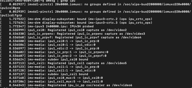
The dmesg output I get related to the display is the following:
[upload|Gl6W/rc9O41cO+wkk6YxD7TJbGQ=]][1]
Sometimes the eht0 link also fails to start right away and I have to give it several tries before it loads. The dmesg output is as follows for that:
[upload|bwnql1LycNg2qvW/ewPOM++vW/w=]
If I run reboot, it seems as if the system never fully restarts as in the display never turns down, but it does. I ran dmesg again to get the same output related to the display.
[upload|7qw38WFGM/6wmwKXTAB6SiILX9Y=]
Hi, @jeremias.tx
After disabling and re-enabling back the overlays, here’s the output of dmesg:
In this state, I can safely reboot and everything works but again, if any power failure occurs, the display goes back to zombie mode.
Hi @jaimeibk,
Your dmesg snippets of the IPU look okay and consistent with what I’d expect.
Though the Ethernet issue is also odd.
I did some investigation on my end using one of our TFT displays, it’s only 18bit so not quite the same but I disabled the weim interface in my setup to try and get as close as I could to your environment.
Unfortunately no matter how I cut the power to my system I’m unable to reproduce your issue.
I don’t think the issue is with the overlays as that wouldn’t make much sense. So the only unknowns that I can’t replicate on my end would either be your display hardware, your custom carrier board, or your display driver software.
My current theory now is that there is something about at least 1 of these 3 components that is causing your system to not be power-cut safe.
Is there any dmesg logs related to your specific display driver, not the IPU but the special driver that you had to compile in?
If not then it might be hardware related, it would be interesting to see if you could replicate this issue on another TFT display if possible.
Best Regards,
Jeremias
HI, @jeremias.tx
It is weird that, somehow, the change in the overlays helps get the display out of the zombie state.
The differences you point out may lead us to something. Let me point a couple of things here:
- Carrier board: it is mostly based upon the evaluation board schematic. I’m going to check schematics again back to back to see if I can find something interesting there.
- Display driver software: this has been happening long before we added the driver software, so I am quite confident this lead is a dead end.
- Display hardware: if this was an issue, it very well may have happened before under WinCE, don’t you think ? I mean, as far as I know, we have not had any problem like this one on WinCE, which makes me think this may not lead us to something interesting.
Can we discard the overlay part altogether? Tomorrow, I will debug the board to see if I can find something else of interest.
Hi @jaimeibk,
You have good points, it’s just I can only speculate possible causes without being able to replicate your issue or setup.
Do you have any Toradex carrier boards rather than just your custom one? If you’re able to replicate this issue on a Toradex carrier (or not) then this can help eliminate one of the differences between our setups.
Best Regards,
Jeremias
Hi, @jeremias.tx
How could we replicate this? Toradex carrier boards can only handle 18bit wiring, right? I don’t think we could do that.
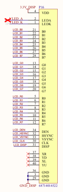
Here are some things we found in the lab along with the connection to our display
:
Basically, it consists of the 8 wires per color channel, backlight and control pins. We analyzed two states: reboot by command line and the faulty state caused by a hard reboot.
Reboot by command line:
On each channel, a stream can be observed on each wire, as expected. Upon reboot, each wire goes from its reset state (H) back to, after a approx 2 secs, streams.
The control pins behave as follows:
- Pin 30 (LCD_CLK): 50MHz clock as defined in a device tree overlay. Pin goes from clock state, to H upon reset (default reset state) back to 50MHz clock.
- Pin 31 (LCD_DISP): this is just an ON/OFF pin hardwired to 3.3V. So, as expected, upon reboot it stays the same in H.
- Pin 32: (LCD_HSYNC): 45kHz signal that goes to H upon reset back again to 45kHz
- Pin 33: (LCD_VSYNC): 83Hz signal that goes to H upon reset back again to 83Hz.
- Pin 34: (LCD_EN): 40KHz signal that goes to H upon reset back again to 40KHz.
Faulty state:
On each channel pin, we can see data streams. On reset, each pin goes to its default reset state, and then each one goes to L.
On the control pins side:
- Pin 30 (LCD_CLK): H upon reset (default reset state) then to L.
- Pin 31 (LCD_DISP): Upon reboot it stays the same in H.
- Pin 32: (LCD_HSYNC): Upon reset it is H and then to L.
- Pin 33: (LCD_VSYNC): Upon reset it is H and then to L.
- Pin 34: (LCD_EN): Upon reset it goes to ~300mV and then to L.
It looks as if the processor ignored its configuration altogether. Curiously enough, this behavior happens just when the 24bit wiring is enabled. When disabled, this never happened.
Even when trying to reset via the RESET_EXT pin, the pattern is the same. It resets fine if there is no active 24bit wiring. When active and the RESET_EXT pin goes low, we lose the display.
I found a custom device tree someone generated in house before I began working here. Is there a way to replace the default device tree so I could test this other one ?
Hi @jaimeibk,
Our Colibri evaluation board should be able to support 24bit RGB displays along the generic RGB display interface X20.
Also thank you for the signal analysis, so it really seems it’s the control pins which aren’t resetting properly. Another point I find interesting is that you mention this only happens with the 24bit configuration. If you could, could you please share all the overlays you are using related to your display? While I only have an 18bit display here, I might be able to gain some insight by playing around with your overlays.
As for adding a completely new device tree binary, on Torizon device trees are loaded at boot from this location on the root file system: /boot/ostree/torizon-{some checksum}/devicetree-imx6dl-colibri-eval-v3.dtb. You just need to replace this file with your new binary.
You mention this device tree was generated previously, so be careful that this device tree is compatible with the current kernel (5.4) running on Torizon or your system will not boot properly.
Best Regards,
Jeremias
Hi, @jeremias.tx
Please find attached the other device trees. link text
I will try to reproduce it using the interface and try the other device tree. I am aware that it may or may not work as intended.
Thanks!
Hi @jaimeibk,
Just an update, I kept getting iomuxc errors after I applied your overlays as is, I modified them slightly to get rid of these errors. Do these errors show up for you?
Moving on, I applied these overlays and tested with my 18bit display on the Colibri Eval board. I still can’t recreate your issue of display failure. I even tried applying the changes to the device tree source directly and recompiled.
This leads me to believe that perhaps this might be hardware related. As we’re using the same OS, overlays, and while we have different displays they both utilize the generic “MIPI DPI Panel Driver” in Linux. So now the only difference in our setups is carrier board and the actual physical display hardware.
Any feedback you might have testing your display on our Toradex carrier board would help narrow the possible root cause further.
Best Regards,
Jeremias
Hi, @jeremias.tx
I could not get rid of those errors even when I redefined the whole iomuxc module. How did you get rid of them?
I will try running the tests with the Toradex carrier board this week. My only drawback is that I need an adapter to use the X20 port on the evaluation board. I will let you know how this goes. Although I am not sure about this being a hardware related problem, because I think we would have had problems with our WinCE applications, don’t you agree?
Anyway, I will keep you posted.
Jaime
Hi, @jeremias.tx
Latest news:
I ran the same tests on the display control lines while running WinCE. Signals were as expected, except that the OS boots back on after a hard reset without any problem.
As for Torizon, I kept digging a bit more to see if I could find something else. The dmesg log shows that after a hard reset the kernel is unable to load several things: rtc ID (which, I believe, is also i2c, iirc?), the touchscreen driver, but also the sgtl5000. This points towards i2c imo. What do you think?
Best regards,
Jaime
Hi @jaimeibk,
You’re reasoning is sound and I myself am not 100% on whether hardware is the issue or not, I’m just trying to narrow the possible differences between our setups.
Since you confirmed that the display resets fine on WinCE, that must mean there is a difference in how Torizon/Linux OS in general handles signals on hard reset. However though you mentioned that this doesn’t happen in the 18bit signal configuration (aka the default with no overlay). Which confuses this further.
As for the edits I made to your overlay this is my version of your 24bit_wiring_test.dts:
/dts-v1/;
/plugin/;

#include "imx6dl-pinfunc.h"


/ {
	compatible = "toradex,colibri_imx6dl", "fsl,imx6dl";
	fragment@0 {
		target = <&ipu1>;
		__overlay__{
			pinctrl_ipu1_lcdif: ipu1lcdifgrp {
				fsl,pins = <
				MX6QDL_PAD_DI0_DISP_CLK__IPU1_DI0_DISP_CLK 0xa1
				MX6QDL_PAD_DI0_PIN15__IPU1_DI0_PIN15       0xa1
				MX6QDL_PAD_DI0_PIN2__IPU1_DI0_PIN02        0xa1
				MX6QDL_PAD_DI0_PIN3__IPU1_DI0_PIN03        0xa1
				MX6QDL_PAD_DISP0_DAT0__IPU1_DISP0_DATA00   0xa1
				MX6QDL_PAD_DISP0_DAT1__IPU1_DISP0_DATA01   0xa1
				MX6QDL_PAD_DISP0_DAT2__IPU1_DISP0_DATA02   0xa1
				MX6QDL_PAD_DISP0_DAT3__IPU1_DISP0_DATA03   0xa1
				MX6QDL_PAD_DISP0_DAT4__IPU1_DISP0_DATA04   0xa1
				MX6QDL_PAD_DISP0_DAT5__IPU1_DISP0_DATA05   0xa1
				MX6QDL_PAD_DISP0_DAT6__IPU1_DISP0_DATA06   0xa1
				MX6QDL_PAD_DISP0_DAT7__IPU1_DISP0_DATA07   0xa1
				MX6QDL_PAD_DISP0_DAT8__IPU1_DISP0_DATA08   0xa1
				MX6QDL_PAD_DISP0_DAT9__IPU1_DISP0_DATA09   0xa1
				MX6QDL_PAD_DISP0_DAT10__IPU1_DISP0_DATA10  0xa1
				MX6QDL_PAD_DISP0_DAT11__IPU1_DISP0_DATA11  0xa1
				MX6QDL_PAD_DISP0_DAT12__IPU1_DISP0_DATA12  0xa1
				MX6QDL_PAD_DISP0_DAT13__IPU1_DISP0_DATA13  0xa1
				MX6QDL_PAD_DISP0_DAT14__IPU1_DISP0_DATA14  0xa1
				MX6QDL_PAD_DISP0_DAT15__IPU1_DISP0_DATA15  0xa1
				MX6QDL_PAD_DISP0_DAT16__IPU1_DISP0_DATA16  0xa1
				MX6QDL_PAD_DISP0_DAT17__IPU1_DISP0_DATA17  0xa1
				MX6QDL_PAD_DISP0_DAT18__IPU1_DISP0_DATA18  0xa1
				MX6QDL_PAD_DISP0_DAT19__IPU1_DISP0_DATA19  0xa1
				MX6QDL_PAD_DISP0_DAT20__IPU1_DISP0_DATA20  0xa1
				MX6QDL_PAD_DISP0_DAT21__IPU1_DISP0_DATA21  0xa1
				MX6QDL_PAD_DISP0_DAT22__IPU1_DISP0_DATA22  0xa1
				MX6QDL_PAD_DISP0_DAT23__IPU1_DISP0_DATA23  0xa1
				>;
			};
		};
	};
};
Do note I worked on just the pin muxing for the ipu and not the GPIOs so I could focus on the display subsystems. I basically just set the target-path to the ipu sub-node directly. When I applied the overlay like this it didn’t return any errors but I also don’t have a 24bit display to test and see if the 24bit changes actually applied correctly.
Finally as for your dmesg errors, could you provide your dmesg or just small snippets to relevant sections as I haven’t seen these errors on my end.
Best Regards,
Jeremias
Hi, @jeremias.tx
–You’re reasoning is sound and I myself am not 100% on whether hardware is the issue or not, I’m just trying to narrow the possible differences between our setups.
I understand. I am still going to run the other tests as soon as I get an adapter so I can connect to the Universal Display Interface.
—…Which confuses this further.
I know. It is mildly infuriating at times, but I am sure we will figure it out.
As for the overlay you edited, I tried using it to no results. I mean, it indeed showed no errors, but did not actually enable the 6 extra wires, so the image is still pinkish. It seems that you have to point first to &iomuxc and then to ipu1 to get the 6 wires working. dmesg will show errors this way, though.
/ {
	compatible = "toradex,colibri_imx6dl", "fsl,imx6dl";
	fragment@0 {
		   target = <&iomuxc>;
		   __overlay__{
			ipu1{
				pinctrl_ipu1_lcdif: ipu1lcdifgrp {
						fsl,pins = <
						MX6QDL_PAD_DI0_DISP_CLK__IPU1_DI0_DISP_CLK	0xa1
						MX6QDL_PAD_DI0_PIN15__IPU1_DI0_PIN15			0xa1
						MX6QDL_PAD_DI0_PIN2__IPU1_DI0_PIN02        		0xa1
						MX6QDL_PAD_DI0_PIN3__IPU1_DI0_PIN03        		0xa1
						MX6QDL_PAD_DISP0_DAT0__IPU1_DISP0_DATA00   	0xa1
						MX6QDL_PAD_DISP0_DAT1__IPU1_DISP0_DATA01   	0xa1
						MX6QDL_PAD_DISP0_DAT2__IPU1_DISP0_DATA02   	0xa1
						MX6QDL_PAD_DISP0_DAT3__IPU1_DISP0_DATA03   	0xa1
						MX6QDL_PAD_DISP0_DAT4__IPU1_DISP0_DATA04   	0xa1
						MX6QDL_PAD_DISP0_DAT5__IPU1_DISP0_DATA05   	0xa1
						MX6QDL_PAD_DISP0_DAT6__IPU1_DISP0_DATA06   	0xa1
						MX6QDL_PAD_DISP0_DAT7__IPU1_DISP0_DATA07   	0xa1
						MX6QDL_PAD_DISP0_DAT8__IPU1_DISP0_DATA08   	0xa1
						MX6QDL_PAD_DISP0_DAT9__IPU1_DISP0_DATA09   	0xa1
						MX6QDL_PAD_DISP0_DAT10__IPU1_DISP0_DATA10 	0xa1
						MX6QDL_PAD_DISP0_DAT11__IPU1_DISP0_DATA11  	0xa1
						MX6QDL_PAD_DISP0_DAT12__IPU1_DISP0_DATA12  	0xa1
						MX6QDL_PAD_DISP0_DAT13__IPU1_DISP0_DATA13  	0xa1
						MX6QDL_PAD_DISP0_DAT14__IPU1_DISP0_DATA14  	0xa1
						MX6QDL_PAD_DISP0_DAT15__IPU1_DISP0_DATA15  	0xa1
						MX6QDL_PAD_DISP0_DAT16__IPU1_DISP0_DATA16  	0xa1
						MX6QDL_PAD_DISP0_DAT17__IPU1_DISP0_DATA17  	0xa1
						MX6QDL_PAD_DISP0_DAT18__IPU1_DISP0_DATA18  	0xa1
						MX6QDL_PAD_DISP0_DAT19__IPU1_DISP0_DATA19  	0xa1
						MX6QDL_PAD_DISP0_DAT20__IPU1_DISP0_DATA20  	0xa1
						MX6QDL_PAD_DISP0_DAT21__IPU1_DISP0_DATA21  	0xa1
						MX6QDL_PAD_DISP0_DAT22__IPU1_DISP0_DATA22  	0xa1
						MX6QDL_PAD_DISP0_DAT23__IPU1_DISP0_DATA23  	0xa1
						>;
					};
				};
		   };
	};
};
link text
Find attached three files. log.txt is what dmesg shows while being 18bit. log24bit is the working 24bit, and the output dmesg shows after a soft reset. Finally, logfaulty is where the good stuff will be. Note how everything running i2c is not running as it should. I mean, the codec should still be working, since there is nothing in the overlays that overlaps with it, right?
Best regards,
Jaime
Hi, @jeremias.tx !!
Thanks. I will test it right away!
Hi, @jeremias.tx !!
I have great news! Not only did the dt work, but it now shows no errors. Hard resets are no longer a problem. Would you mind sharing the dts?
I guess the overlay was not working as we thought, somehow.
Best regards,
Jaime
@jaimeibk,
That’s great news, glad we were able to narrow down the root cause to the overlay.
At the moment I’m not sure why the overlay wasn’t working properly, something I need to investigate. Unfortunately device tree overlays is something that is not well documented by the Linux community at large.
As for the device tree here’s a diff of the changes I did on my side: https://share.toradex.com/iszk0qpdf4h9zyj
Just to be clear these changes apply to the toradex_5.4.y branch of the Toradex Linux Kernel.
Best Regards,
Jeremias