Hi, We are using Verdin + Dahlia combination loaded with “Boot2Qt 6.2.1 Toradex Verdin-iMX8MP” linux image. I need to view and modify the device tree. I am new to Linux systems. I went through “High performance, low power Embedded Computing Systems | Toradex Developer Center” link to have some initial understanding and it says that device tree is located under arch/arm/boot/dts/ folder. When I checked my board, i could not find the arch folder. PLease suggest how to locate and modify the device tree. Also this board does not take any basic command like apt, apt-get, sudo etc. I want to use these commands to install the dtc compiler.
All the modifications in the device tree are done inside your host computer (Linux or Windows) instead of the board. You will compile the device tree on your computer and then copy it to your board. The module doesn’t have all the necessary tools to compile it and usually, our desktop computers have better hardware to do that.
Thanks for your quick response. I went through the “Build From Source Code Documentation Overview | Toradex Developer Center” link and found that I need to have the required setup in host computer (not sure, if this link can be followed for windows host ?). This setup requires the BSP package, kernel code from Toradex’s website.
We are using Verdin+Dahlia loaded with Boot2Qt 6.2.1. We built this image from the Boot2Qt software stack. Can we modify the device tree for this setup using the host setup that is created per above link ?
As per my understanding it will create conflict right ?
Our main problem statement is - We want to check one of the GPIOs if that is properly set in device tree because we are not able to toggle this output GPIO. Please suggest how we can debug the issue.
For a windows host computer, the better approach would be to use WSL or a Linux Virtual Machine in this case.
If you follow the above link to set everything and modify the device tree, it should work on your image as well. You just need to make sure that you get the right files for your module and modify them accordingly to your needs.
Could you share with me which pin are you trying to debug? One way to do that would be to check the device tree that you are using. This pin will be assigned inside of this file.
If you follow the above link to set everything and modify the device tree, it should work on your image as well. You just need to make sure that you get the right files for your module and modify them accordingly to your needs.
I went through section “Deploying the Kernel to an Image” of article and found that it integrates modified Kernel with Toradex’s image which makes sense. In my case, do I need to have my Boot2Qt image in the download folder ? Also Will the instructions mentioned in the link also applicable to my boot2qt image creation setup (I am using Boot2Qt software stack).
Could you share with me which pin are you trying to debug? One way to do that would be to check the device tree that you are using. This pin will be assigned inside of this file
It is GPIO4_IO26 pin. Could you please assist more in how to check the existing device tree which is running on the target ?
Yes, the linux kernel should be inside your image folder, so you can follow the same principle from our reference images. You can also show me which files are inside your folder so I can assist you with that.
This pin isn’t enable by default. Checking the Verdin iMX8M Plus datasheet, this GPIO4_IO26 is located at pin 24, which is CAN2_TX by default.
In order to use this pin as GPIO, you can create an overlay or change the device tree to enable this function. An overlay should look as the following code.
Please note that this is just an example, but something like this modification is required. I would recommend using a different GPIO which is already available, so no modification is needed.
My understanding is - QT shall use the Toradex’s device tree only then can we modify required toradex’s device tree file and load only that on the target board ? If yes, how it can be done. Also if we go with separate device tree overlay then how it can be loaded into target board. Please suggest.
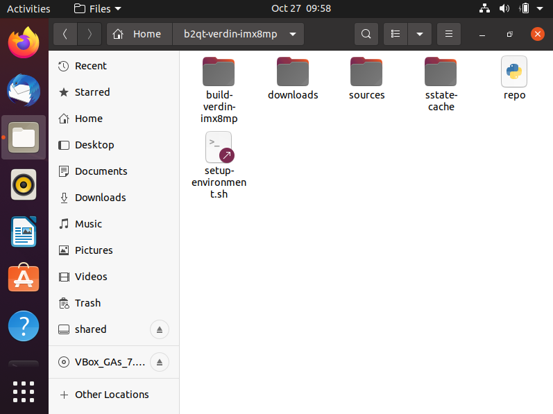
The image looks like the folder for the Yocto build, am I correct?
The image should be inside the build folder, usually, it’s a compressed tar file where all the files for the OS (kernel, device trees), are inside.
I would say the same, they’re using the same device tree. This image is actually managed by the QT company and it’s the build, it’s not strictly under the Toradex domain. We offer support for TorizonCore and our BSP layers, while QT offers support for their boot2QT image.
Despite that, it should be similar to what we do in our images.
This overlay should work for you to enable the GPIO if QT is using the device tree that we provide. Assuming this is correct, you can compile this code and send it to your module (using a USB stick or copying through the internet with the SCP command). Then, you will copy the compiled binary to the /boot/overlays folder and paste the name of the file inside /boot/overlays.txt. It should look like this:
I’ve also successfully compiled the .dts file and received the .dtbo file. I placed the .dtbo file onto a flash drive and copied it over onto the SOM.
The work instruction mentioned to copy the .dtbo file over into the /boot/overlays folder and append the /boot/overlays.txt file, but this file and directory did not exist. Our /boot/ directory looked like:
Instead, I found an overlays folder and overlays.txt file located under /media/mmcblk2p1
So, I copied the .dtbo file to the /media/mmcblk2p1/overlays/ folder and appended the /media/mmcblk2p1/overlays.txt file.
Does this seem correct?
This seemed to work, but there is no longer any HDMI output. I can confirm that the kernel is still booting via the serial output. The overlay file appears to be implemented though. Within the overlay .dts file, if I set the pin configuration to 0x104 (pull down resistor), I measure 0V on the Dahlia X19 pin 1 when the OS boots. If I set the pin configuration to 0x144 (pull up resistor), I measure 1.8V on the Dahlia X19 pin 1 when the OS boots. However, there is still no HDMI output. If I remove the .dtbo reference from the overlays.txt file, the HDMI functionality returns.
I wanted to check-in with a quick update. I played with this some more and it appears to be functioning properly now (HDMI too).
It looks like the particular SOM that I’m using is the non-wifi version. I was browsing the forums and found another thread where someone posted a sample dts file for a non-wifi SOM. It had some additional tweaks. My dts file now looks like:
I’m still working to understand what these differences are actually doing and why they are different for the wifi/non-wifi versions, but I just wanted to provide an update that it appears to be working properly!
The CTRL_WAKE1_MICO# appears to be capable of being used as an input and a wake up pin.
As far as configuring this in the device tree overlay, can you give me an example of what this might look like? I successfully configured it as a GPIO using the same DTO, but I’m losing the wake up capability. Surely I am missing something, but I’m a little stuck.