There is a way to increase the clock low time between the bytes in the SPI frame?
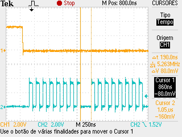
In the images attached is possible to see that the oscilloscope first channel (spi clock) has a short time between end of one byte and the beginning of the sequential one.
[upload|wwCjsYksrYodsuarW18iuvphCIE=]
Because of this characteristic, I’m losing the first bit of the byte, oscilloscope second channel signal, since its time is lower than the necessary time request by the chip to change the SO output.
[upload|7koEXKpGFfWjWZKhXI8+SYaa5IE=]
Which image version are you using? What is the output of
uname -a
cat /etc/issue
Angstrom v2015.12 - Kernel
Colibri_VF_LinuxImage-qteV2.6.1_20170112
Linux colibri-vf 4.4.39-00830-g418f717-dirty #1 Thu Jan 12 11:35:57 BRST 2017 armv7l GNU/Linux
Can you try by setting the delay_usecs parameter in spi_ioc_transfer structure of your application?. This should result in a delay being introduced between two transfers by the driver here.
There are also other optional properties for device tree which might interest you.
Hi,
If I understand right, the optional property delay_usecs is used to insert a delay between transfers, where a transfer is composed by n bytes.
The issue I have is kind of different, I need to insert a delay between the bytes in a transfer, or just keep the negative pulse time of the clock symmetry between the bytes in the transfer.
And which is the image version you use? Note that there are SPI DMA fixes in the 2.7 image version and if you are using 2.6, you either need to use an updated kernel or use the latest 2.7 release.
Hi @gafernandes, I’m facing the same issue here. I’ve analyzed the data using Saleae Logic Analyzer and one Oscilloscope, and this is quite annoying, seeing the same pattern as you. If I transfer a lot of bytes in a Chip-Select, there is a clock “mess” between consecutive bytes. How this could be fixed? Thanks, Andre Curvello
Hi @andrecurvello and @sanchayan.tx,
I’m not using DMA (see spi config from dts below). About the kernel, I’m using the latest committed one, from branch toradex_vf_4.4-next, that have the spi update fixes.
    	spidev0: spidev@0 {
    		compatible = "toradex,evalspi";
    		reg = <0>;
    		spi-max-frequency = <1000000>;
    		dma-names = " ", " ";
    	};
Just some thoughts about the issue:
I don’t believe that this is a issue related to delays, that can be configured int he VF6xx CTAR register. Since, delay configurations are related to delay from CS selection and beginning of the SCLK pulses, end of the SCLK pulses and dessert of CS and between the end of a CS and the beginning of the next CS.
Maybe something related to the configuration of SCLK??
@sanchayan.tx I’m using the toradex_vf_4.4-next image too.
Hi @sanchayan.tx,
I will post the methods I’m using to configure the SPI port, and the write and read methods to access the DAC7760 device. Using this code, I can reproduce the issue every time. Maybe, something is missing in the SPI configuration or in the XFER struct.
int DAC7760::configure(char *spi_dev_path)
{
    u_int32_t   mode = 0;
    u_int32_t   speed;
    u_int8_t    bits;

    if ((this->fd = open((const char *)spi_dev_path, O_RDWR)) < 0)
    {
        return ERROR_DAC7760_OPEN;
    }
    else
    {
        /*
         * spi mode
         */
        mode = SPI_MODE_0;
        if (ioctl(this->fd, SPI_IOC_WR_MODE32, &mode) < 0)
        {
            return ERROR_DAC7760_SET_MODE;
        }

        /*
         * bits per word
         */
        bits = 8;
        if (ioctl(this->fd, SPI_IOC_WR_BITS_PER_WORD, &bits) < 0)
        {
            return ERROR_DAC7760_SET_WORD_SIZE;
        }

        bits = 8;
        if (ioctl(this->fd, SPI_IOC_RD_BITS_PER_WORD, &bits) < 0)
        {
            return ERROR_DAC7760_SET_WORD_SIZE;
        }

        /*
         * max speed hz
         */
        speed = DAC7760_MAX_FREQ;
        if (ioctl(this->fd, SPI_IOC_WR_MAX_SPEED_HZ, &speed) < 0)
        {
            return ERROR_DAC7760_SET_BUS_FREQUENCY;
        }
    }
    return OK;
}

int DAC7760::readRegister(u_int8_t reg_add, u_int16_t *value)
{
    u_int8_t    bufOut[WRITE_SIZE];
    u_int32_t   sizeBufOut;
    u_int8_t    buf[WRITE_SIZE];

    struct spi_ioc_transfer	xfer[1];

    memset(xfer, 0, sizeof xfer);
    memset(buf, 0, sizeof buf);

    // inicia contador do tamanho do buffer de envio
    sizeBufOut = 0;

    //monta mensagem
    bufOut[sizeBufOut++] = READ_REGISTER; // registro a ser lido
    bufOut[sizeBufOut++] = (u_int8_t)((reg_add >> 8) & 0xFF); // bits 15..8
    bufOut[sizeBufOut++] = (u_int8_t)(reg_add & 0xFF); // bits 7..0


    xfer[0].tx_buf = (unsigned long)bufOut;
    xfer[0].rx_buf = (unsigned long)NULL;
    xfer[0].len = sizeBufOut;
    xfer[0].cs_change = true;

    if (ioctl(this->fd, SPI_IOC_MESSAGE(1), xfer) < 0)
    {
        return ERROR_DAC7760_READ_REGISTER;
    }

    /*
     * para realizar a leitura do registro, eh necessario utilizar um xfer
     * unico, pois apos escrever o endereço a ser lido, o chip select tem
     * que mudar de estado e depois ser realizada a leitura do registro
     */


    //preenche escrita com 3 bytes = 0x00
    sizeBufOut = 0;
    bufOut[sizeBufOut++] = NO_OPERATION;
    bufOut[sizeBufOut++] = NO_OPERATION;
    bufOut[sizeBufOut++] = NO_OPERATION;

    xfer[0].tx_buf = (unsigned long)bufOut;
    xfer[0].rx_buf = (unsigned long)buf;
    xfer[0].len = sizeBufOut;
    xfer[0].cs_change = true;

    if (ioctl(this->fd, SPI_IOC_MESSAGE(1), xfer) < 0)
    {
        return ERROR_DAC7760_READ_REGISTER;
    }

    return OK;
}


int DAC7760::writeRegister(u_int8_t reg_add, u_int16_t value)
{

    struct  spi_ioc_transfer	xfer[1];
    u_int8_t    bufOut[WRITE_SIZE];
    u_int8_t sizeBufOut = 0;

    memset(&xfer[0], 0, sizeof(struct spi_ioc_transfer));

    //monta mensagem
    bufOut[sizeBufOut++] = reg_add; // registro a ser escrito
    bufOut[sizeBufOut++] = (u_int8_t)((value >> 8) & 0xFF); // bits 15..8
    bufOut[sizeBufOut++] = (u_int8_t)(value & 0xFF); // bits 7..0

    xfer[0].tx_buf = (unsigned long)bufOut;
    xfer[0].rx_buf = (unsigned long)NULL;
    xfer[0].len = sizeBufOut;
    xfer[0].cs_change = true;

    if (ioctl(this->fd, SPI_IOC_MESSAGE(1), xfer) < 0)
    {
        return ERROR_DAC7760_WRITE_REGISTER;
    }

    return OK;
}
Can you also check with DMA mode enabled by removing your dma-names addition to spidev node?
Hi @gafernandes e @sanchayan.tx
Do you have any news about this topic?
Thanks for your attention.
Is your issue exactly the same as for @gafernandes? Do you also not use DMA and use EOQ mode? Does it work for you with DMA mode? Which exact device do you try to communicate with?
@gafernandes Can you please check with DMA mode enabled and also a higher clock rate in EOQ mode if possible?
Hi @sanchayan.tx
Please, is possible for you to send an example in how to configure DMA in the interfaces below?
To enable EOQ mode, requires only the variable “eoq-mode;” in the body of the declaration below?
&dspi1 {
	bus-num = <1>;
	pinctrl-names = "default";
	pinctrl-0 = <&pinctrl_dspi1>;
	status = "okay";

	spidev0: spidev@0 {
		compatible = "toradex,evalspi";
		reg = <0>;
		spi-max-frequency = <1000000>;
		dma-names = " ", " ";
	};

	spidev1: spidev@2 {
		compatible = "toradex,evalspi";
		reg = <2>;
		spi-max-frequency = <1000000>;
		dma-names = " ", " ";
	};
};
Regards,
I would first recommend trying a higher clock frequency like 10 MHz.
Having the below
dma-names = " ", " ";
will use the EOQ mode. To use DMA mode just remove dma-names property specification.
Also please make sure that you use the toradex_vf_4.4 branch.
@sanchayan.tx And that can be used for all the SPIs presents in the VF61?
I faced a issue related to SPI Clock in this topic:
https://www.toradex.com/community/questions/7009/spi-keeps-sending-clock-and-mosi-data-after-chip-s.html
But for now I’m facing something quite similar to @gafernandes, which is the “fuzzy clock” between word in a chip-select transfer.
I’ll test with your suggestion.
@gafernandes, just for some clarification: the blueish (turquoise) signal is MOSI (data), yellow is clock? So you transfer a 0 and then a 255 subsequently?
Also, what are your CPOL/CPHA settings? It seems to be CPOL=0, CPHA=0, does that match your device?
I agree, the clock looks a bit quirky between the transfers, but it seems to me that when you sample on falling edge it still should get that first bit…
So to confirm, using the device tree properties fsl,spi-cs-sck-delay and fsl,spi-sck-cs-delay as mentioned here fix the issue for you?
Hi @sanchayan.tx and @andrecurvello,
I change the clock to 10MHz as suggested and the delays between the words turn to about 50ns. But till this, the problem I have persist. So, with a close look, I see that the time from rise of the CS to the start of the clock positive clock pulse was 20ns. So, I decide to use the variables fsl,spi-cs-sck-delay and fsl,spi-sck-cs-delay, to delay the start of the clock and end of the clock from the moments of CS. The result of this was not only the delay in the start and end of the transfer as expected, the sum of the delays appears between each word as well. And now I can read the values correctly.
I set 100ns to fsl,spi-cs-sck-delay and 50ns to fsl,spi-sck-cs-delay.
See the captured images bellow: