We are currently using the Verdin iMX8MM Q 2GB IT (V1.1C).
We have noticed that a low signal at the CTRL_RESET_MICO# pin is ignored during power-up and the Verdin module is not held in reset state. The Verdin is then started up for approx. 50ms (CTRL_PWR_EN_MOCI, etc. goes high) until the reset signal debounced is recognized by the PMIC on the Verdin, which then pulls the module into reset.
Is this behavior intentional?
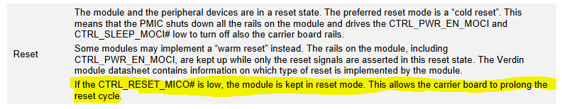
If the reset signal (CTRL_RESET_MICO#) goes low in normal operation, the Verdin behaves as expected: It is held in reset until the reset signal is released again.
You can find the explanation of the signal timings in our verdin carrier design guide. page 77.
"
The Verdin module starts the power-up sequence when the VCC main input voltage is applied.
There is no need to press the power button signal (CTRL_PWR_BTN_MICO#) for starting the
module. The module ramps up early rails on the module. At this point, the pull-up resistors for the
CTRL_PWR_BTN_MICO# and CTRL_RESET_MICO# get enabled. The CTRL_FORCE_OFF_MOCI#
signal goes high. Before enabling these early rails on the module, the signal can be undefined.
Therefore, the carrier board needs to blank (ignore) the CTRL_FORCE_OFF_MOCI# for the first
400ms after VCC has been applied.
After the early module rails are ramped up, the Verdin module outputs the PWR_1V8_MOCI#
output rail and releases the CTRL_PWR_EN_MOCI. The CTRL_PWR_EN_MOCI is used for ramping
up the carrier board rails. The module is enabling all the rest of the rails that are required for the
module to be able to boot up.
After all rails are ramped up and settled, the SoC reset is released together with the
CTRL_RESET_MOCI# for the carrier board. The module determines the length of the delay between
enabling CTRL_PWR_EN_MOCI and releasing the carrier board reset. The carrier board must be
ramping up the voltage rails within 10ms after the CTRL_PWR_EN_MOCI is released.
"
Then this statement only applies if the verdin module is already running. When I look at the “Module Power States and Transitions” diagram, there is no direct path from “No-VCC” to “Reset”.
It is actually true that we do not specify how the module should behave if the reset button is pressed while the power is applied. For the Plus and the Mini, it would be normal for the PMIC to ramp up the rails even though the reset button is kept pressing.
this is because it could be different for other processors. On the AM62, the behavior is actually different. The reset input of the AM62 is edge-sensitive, not even level-sensitive. This means you cannot hold the reset button to prolong the reset cycle.
So you should develop your system according to the defined behavior.
If you need a call to discuss your boot-up process or carrier design let me know. we can set up a carrier board design call.
ok great to hear. keep in mind that we also offer free 30-minute carrier design training and schematic reviews on request.
This helps to reduce your time to market and we can reduce the number of design spins.