How to connect ULINK to Colibri iMX7. I did not find a description of six test points on the Colibri module (TDO, TCK, TDI, TMS, TRST, MOD, GND?). Can you tell me how to connect Colibri with ULINKpro D (pin-to-pin)?
Thanks.
Jaro.
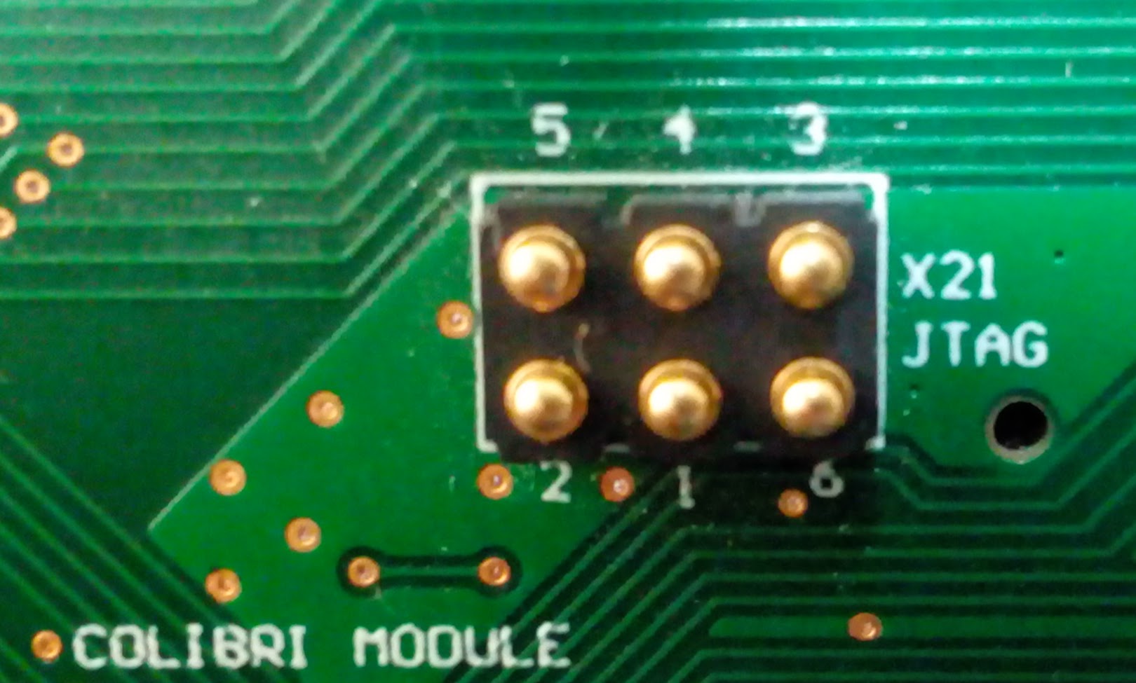
The JTAG interface is located on test points on the underside of the module. You should use Colibri Evaluation Board to access it. And keep jumper JP29 in position 2-3. Find more information here.
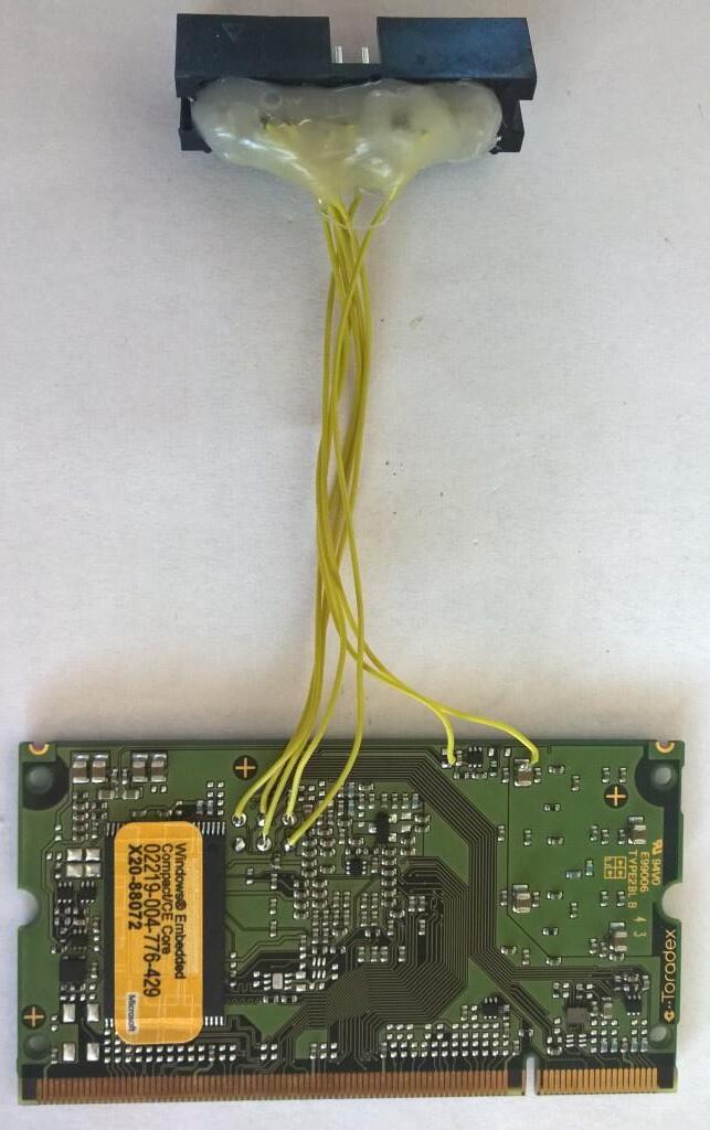
I need to solder JTag connector directly on Colibri module. I want to debug M4 core on my device. I need to know, what are pin numbers. For example a = pin 1 JTAG TDI, b = pin 2 JTAG TDO,… And I also need to know where on module I can solder wire for signal JTAG SYSRESET, VREF and GND. Can you tag them in the photo of the module?
Jaro.
May I know which Carrier board you are using ?
I’m afraid you will void the warranty by doing that.
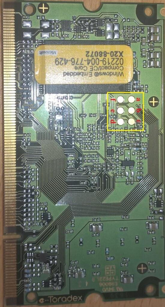
JTAG pogo pin header pin-out information is as follows.
1 | e | TDI
2 | d | TDO
3 | a | TCK
4 | b | TRST#
5 | c | TMS
6 | f | NC
Can you tag in the photo of the module where should I connect VREF (+3,3V) and GND for JTAG? If I get it right from Evaluation Board layout I don’t need any JTAG SYSRESET signal for JTAG on iMX7 because it is not needed.
I am using Carrier Board Iris. Thanks to the Evaluation Board photo I know now which test pin is which. ![]() I count on forfeiting the guarantee.
I count on forfeiting the guarantee.
True table is (PCBs are attached to each other. One PCB must turn mirror.):
1 | e | TDI
2 | d | TDO
3 | a | TCK
4 | b | TRST#
5 | c | TMS
6 | f | NC
Can you tag in the photo of the module where should I connect VREF (+3,3V) and GND for JTAG?
You can take any 3v3 available on Iris Board as VREF. Refer Iris schemacits for 3v3 and GND availablity on headers.
I am using Carrier Board Iris. Thanks to the Evaluation Board photo I know now which test pin is which.
I count on forfeiting the guarantee. True table is (PCBs are attached to each other. One PCB must turn mirror.):
My bad, you are correct, it is mirrored wrt to your naming on module. I too updated my table.