We will include a 1:2 PCIe clock buffer to provide REFCLK to both slots.
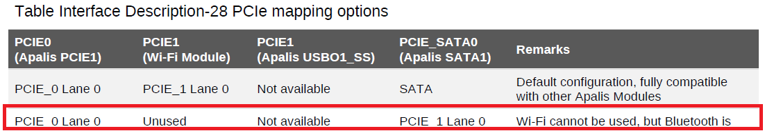
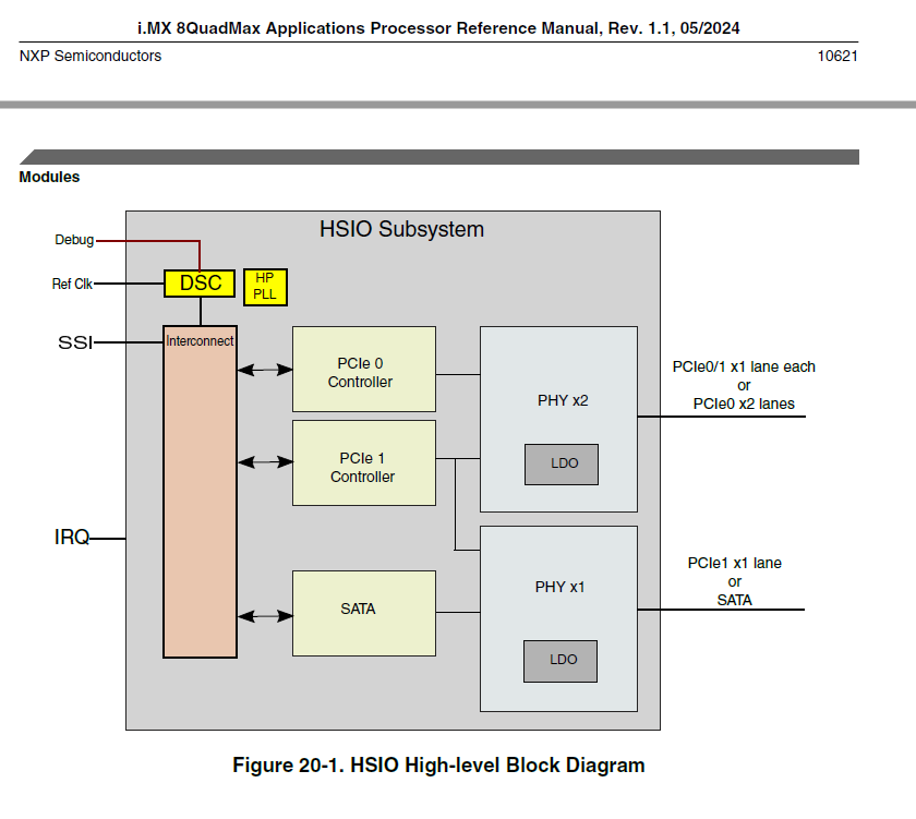
The M.2 will utilize Apalis PCIE1 (PCIe 0 Controller Lane 0 via PCIE0 PHY).
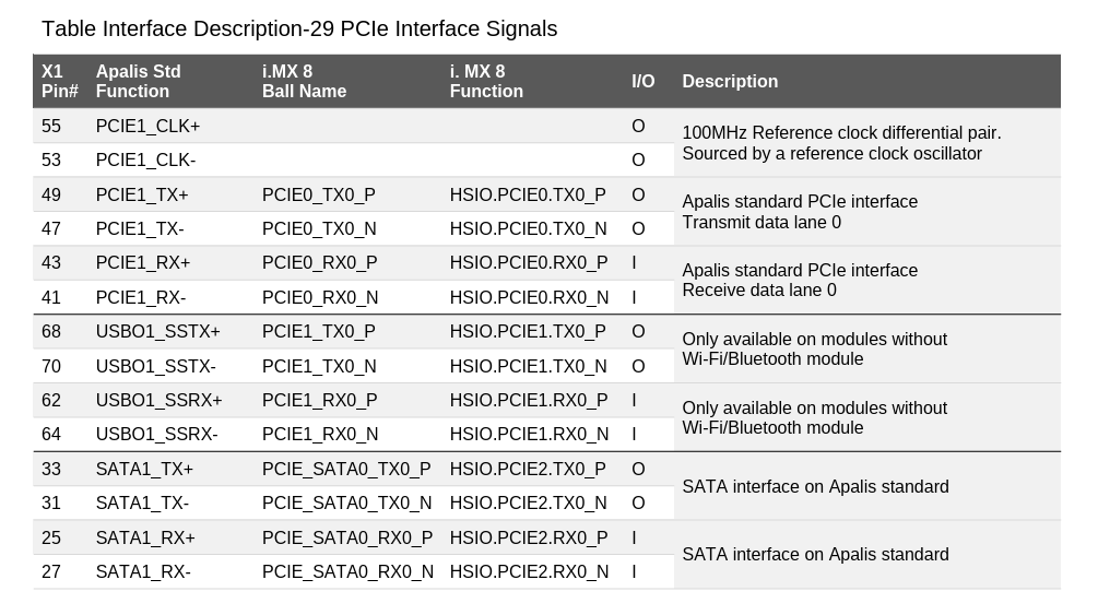
The mPCIe will utilize Apalis SATA1 (PCIe 1 Controller Lane 0 via PCIE_SATA0 PHY), which is the source of my question. I read in the Apalis Carrier Board Design Guide section 2.3.2.1 that both the SATA RX and TX lines include 10nF AC coupling capacitors. In the case of the TX, 10nF would be lower than the typically recommended 100-200nF AC coupling. In the case of the RX, again 10nF is too low, and additionally an mPCIe card will have TX AC coupling capacitors installed already, so this line would have double AC coupling capacitors.
Is there any guidance for how to make use of this configuration?
Is PCIe over the SATA lines known to work in a standard mPCIe configuration even with the 10nF capacitors present? At Gen3/Gen2/Gen1? We can tolerate downgrading the link to Gen2 or Gen1.
If this is expected/known to be an issue, what are the suggested solutions/workarounds? Could a PCIe redriver such as PI2EQX862 or DS80PCI102 be used to clean up the mismatched AC coupling?
I might make mistakes or occasionally get you wrong. Our support team will step in if needed.
Based on the information available in the Toradex documentation, I can provide some guidance on PCIe layout requirements that apply to your carrier board design.
PCIe Layout Requirements
According to the Toradex layout guidelines, PCIe interfaces have specific AC coupling requirements(1). For PCIe connections, the standard requirement is 100nF ±20% AC coupling capacitors in discrete 0402 packages(1). The documentation specifies that PCIe supports Polarity Inversion, meaning positive and negative signal pins can be inverted to simplify layout routing(1).
Key PCIe layout parameters from the documentation include(1):
Trace Impedance: 90Ω ±15% differential; 50Ω ±15% single ended
Max intra-pair skew: <1ps = 150μm
Max trace length skew between clock and data pairs: <1.6ns = 240mm
AC coupling capacitors: 100nF ±20%, discrete 0402 package preferable
Maximum allowed via: 2 vias for TX traces, 4 vias for RX traces (device-down), 2 vias for RX traces (PCIe slot connector)
Addressing Your Specific Questions
Unfortunately, I don’t have specific documentation covering the exact scenario you’re describing with the SATA lines being repurposed for PCIe with 10nF capacitors, or detailed guidance on using PCIe over SATA interfaces with mPCIe cards.
For your specific implementation questions regarding:
Guidance for PCIe over SATA lines configuration
Known compatibility with 10nF capacitors at different PCIe generations
Solutions for AC coupling mismatches and PCIe redriver usage
I’d recommend checking these potentially helpful resources:
Would you like me to provide a general answer based on my knowledge instead, or do you have additional specific documentation about your Apalis iMX8QM module that might contain more detailed information about this particular PCIe mapping configuration?
Best regards, Toradex AI Assistant.
Did you like my answer?
If I answered your question, please tick the “Solution” checkbox.
For follow-up questions to me, please use @ToradexAI in your post.
Unfortunately, we have never tested this configuration and do not have any guidelines available for it.
Sorry for the confusion. The SATA TX lines use 100 nF capacitors (not 10 nF as stated in the design guide). The PCIe TX lanes use 220 nF AC coupling capacitors.
If you require two single-lane PCIe interfaces, there is no need to use the SATA lines. On Wi-Fi-less modules, both PCIe lanes are available on the module edge connector along with SATA.
We can offer this configuration as a custom order. Please use the “Configure Your Own Apalis iMX8” option on the product page below to submit an inquiry, and our sales team will follow up with feasibility and MOQ details: https://www.toradex.com/computer-on-modules/apalis-arm-family/nxp-imx-8
Yes, the USBO1 TX (SuperSpeed) lanes include on-module AC coupling capacitors (220 nF). The RX lanes do not include coupling capacitors.
I do not have direct experience with PCIe redrivers, so I cannot provide specific guidance on their implementation. However, from a general perspective, please ensure the redriver supports the required PCIe generation and link budget, and that placement and routing follow the vendor’s layout recommendations to avoid signal integrity issues.