We have a self-developed board on which an Apalis imx6 runs.
It has a USB-C socket and an onsemi FUSB303 for automatic configuration of the ID pin. When the system (BSP 5.7.1) has started, I can plug in and use a USB stick without any problems (host mode). The gadget mode only works if the other side is plugged in before the boot. After some trial and error, the gadget is restarted if the cable is disconnected and reconnected within a few seconds. Also, instead of rebooting the Apalis, it is sufficient to reload the kernel module ci_hdrc_imx.
Here is an excerpt from the device tree (derived from the ixora carrier board):
®_usb_otg_vbus {
status = "okay";
};
&usbotg {
vbus-supply = <®_usb_otg_vbus>;
status = "okay";
};
What can we do to use the gadget mode during operation. With other products we have a dedicated USB-B socket for this case, without switching. But this should be omitted. It seems like there is a driver bug. Because under /sys/kernel/debug/ci_hdrc.0/role the entry changes as expected according to the connected device.
Just for the record, did you already see this article about USB gadget mode?
If I understand correctly, the connection between host and gadget has to be already connected together before the boot to make it work. If you plug either side in after boot it does not work. Am I correctly understanding?
Sorry for the delay. Most of my team are attending the Embedded World in Nuremberg.
Would you be willing to share a snipped of your schematic where we could see how you implemented the USB port? If you prefer I can make this topic private, if you think the information might be confidential.
could you provide us a more complete schematic ? You can send it to support@toradex.com and please mention this ticket.
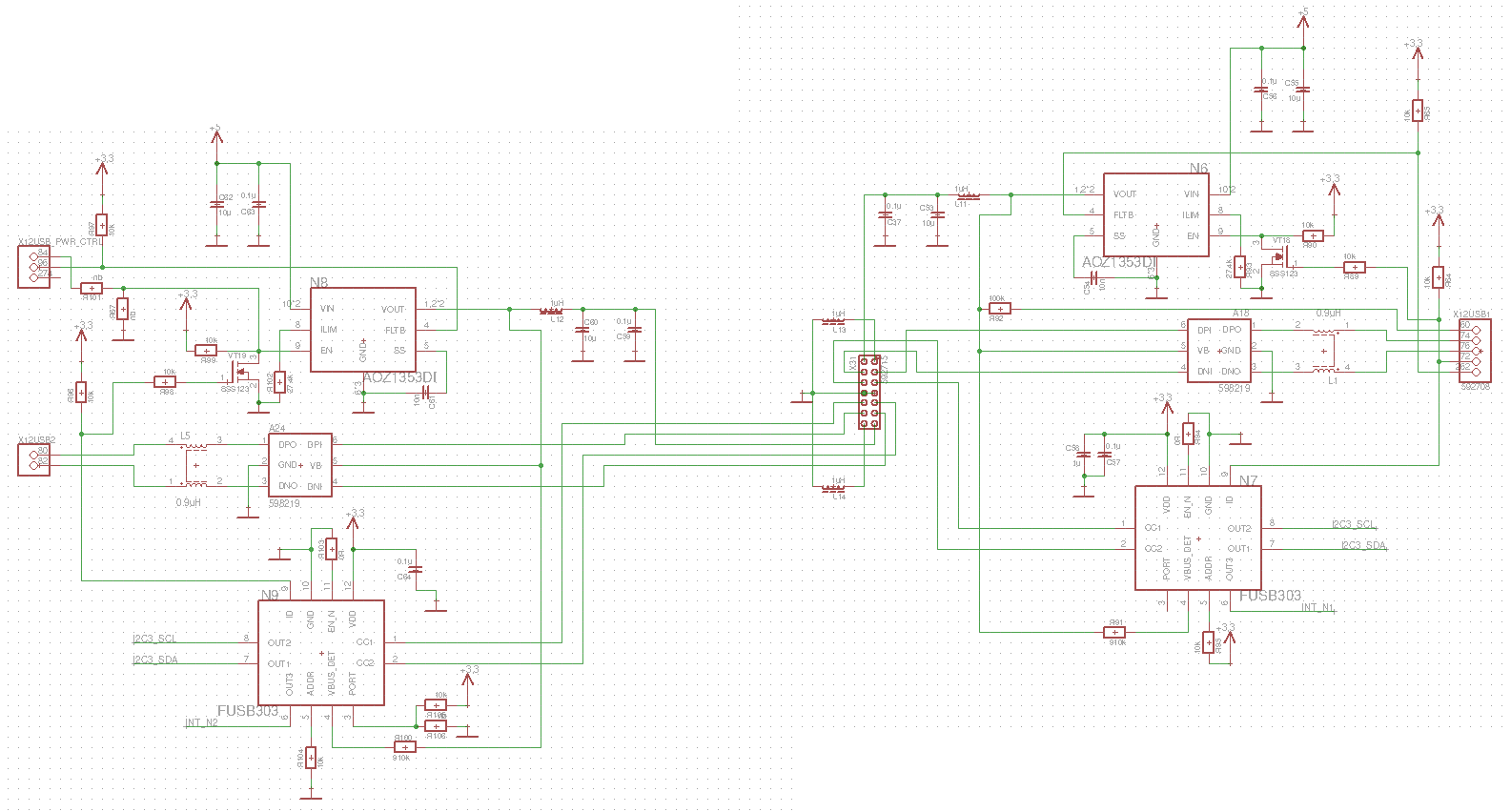
The FUSB303 knows two modes, the I2C mode, and the GPIO mode. Unfortunately, the schematics are incomplete to recognize the whole circuit. But I guess you are using the FUSB303 in the I2C mode. It looks like the ID output of the FUSB303 is connected only to the power switch, and not to the Apalis module. Therefore, the Apalis module would need to read the I2C port for knowing whether the USB-C role changes. I guess this reading is not happening when you plug a USB-C cable. Therefore, the state of the USB port is only red during rebooting or reloading the kernel.
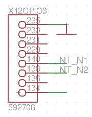
The FUSB303 features an interrupt pin (OUT3). I do not see whether you have connected this pin to the Apalis module. This pin should be used for triggering the reading of the FUSB303 state over the I2C interface. If this interrupt signal is not connected, the Apalis module would need to permanently poll the I2C registers in order to know that the state of the USB-C port has changed and the roles need to be changed.
Why do you use the I2C mode in the first place? The FUSB303 supports a GPIO mode which works very similarly to the TUSB321 detection chip we use in our reference design. Please have a look at the schematic example in Figure 26 of the Apalis design guide (https://docs.toradex.com/101123-apalis-arm-carrier-board-design-guide.pdf). In this example, we do not use the I2C interface for USB-C configuration IC. We are connecting the ID pin with the ID input of the Apalis module. Depending on the level of the ID input, the Apalis module will switch between host and client mode and enable the VBUS switch (USB_1_EN) according to the role. The USB_1_BUS voltage input is required in the client mode for detecting whether a host has been connected to the system.
Let me do a little bit of clarification:
Originally we had the FUSB303 running in i2c mode. Since no communication via i2c was established, we decided to remove the pull-down on pin 5 and are now using GPIO mode. There was no updated schematic yet, so I corrected this with a photo tool.
Please excuse me for showing the wrong USB part of the schematic. Here is everything that belongs to the USB. The (host / client) switchable part should be on the right.
to get the bigger picture we need the schematic as PDF. Otherwise, we might miss things and the Problem will not be discovered.
In the later picture, we realized that there are two USB-C on the left side. Do you only have a problem with the left side? The left side is marked with USB2 and the right side with USB1. Does that mean that you connected the left side with the Apalis USBH2 Port? If yes this can not work. This port is going over a hub inside the Apalis and therefore does not support client mode.
We are using USB1 (right side) for OTG mode. We are aware that only this port can be used for this purpose. Otherwise I would not have succeeded but the client mode also at a restart . I had already written that I am sorry that I posted the wrong part in the first picture. The complete schematic is on the way in a few minutes by mail.
We have experimented a little and on your advice we measured the voltage before and after the series resistor (R92) in the USB01_VBUS line. This was limited to about 3.9V. With a 0Ohm or 10kOhm (~4.97V at the Apalis) resistor the circuit works the circuit works as desired.