Hello,
I am working with a custom board and with a Verdin iMX8M Plus, and it’s not recognizing a USB device on the USB_1 interface.
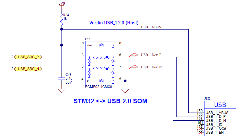
The device on the custom board is a STM32 microcontroller (configured as a CDC). It is connected to the Verdin’s USB_1 interface with the USB_1_D_N and USB_1_D_P pins (pins 163 and 165), attached is a snapshot of this part of the custom board schematic. We have nothing connected to Verdin pins 155, 157, and 161 at the moment. Is is important to have the _OC# (pin 157) pulled high, or to have the other pins connected?
I have a Dahlia carrier board and with that can see USB CDC devices plugged into the X3 connector. From looking at the schematic (for how the USB_1 is connected to the X3 USB-C connector) the status of pin 157 (or 166 or 161) is my guess for the issue.
Thanks for any advice,
Greg Mitchell
Here’s the output of tdx-info:
Software summary
Bootloader: U-Boot
Kernel version: 5.15.129-6.4.0+git.67c3153d20ff #1-TorizonCore SMP PREEMPT Wed Sep 27 12:30:36 UTC 2023
Kernel command line: root=LABEL=otaroot rootfstype=ext4 quiet logo.nologo vt.global_cursor_default=0 plymouth.ignore-serial-consoles splash fbcon=map:3 ostree=/ostree/boot.1/torizon/460c0c1dde52ce6a4fd14e6ff7399ad1c879175a9ffa047acbb97523d9376591/0 galcore.powerManagement=0 galcore.showArgs=1 galcore.gpuProfiler=1
Distro name: NAME=“TorizonCore”
Distro version: VERSION_ID=6.4.0-build.5
Hostname: verdin-imx8mp-15128064
Hardware info
HW model: Toradex Verdin iMX8M Plus WB on Verdin Development Board
Toradex version: 0070 V1.1A
Serial number: 15128064
Processor arch: aarch64
The USB_1 is a Dual Role interface and can act as a host or client. According to the Verdin Carrier Board Design Guide:
“The USB_1_ID signal is used to detect which type of USB connector is plugged into the OTG jack
(Micro-AB jack). When a Micro-A connector is inserted, the ID pin is connected to signal ground,
causing the OTG port to be configured as a host. If a Micro-B USB connector is inserted, the ID pin
is left unbiased, and the OTG port is configured as a client device.”
Given that a Micro-A connector is not being used, the USB_1_ID signal should be grounded to configure the USB_1 interface as a host.
Also from the guide:
"The USB_1_OC# signal is used to notify the module that an over-current condition has occurred. This signal is active-low and requires a pull-up resistor to 1.8V on the carrier board. "
Thus, the USB_1_OC# must be pulled up to the 1.8V rail on your carrier board.
Regarding the USB_1_VBUS circuit, there seems to be an issue. While I am not certain about the VBUS signal requirements for STM32, the USB specification requires it to supply sufficient power for the entire USB device (at least 100mA). If the STM32 draws such a current from VBUS, achieving this through a 1K resistor is likely impractical
Hi Alex,
That’s done the trick and fixed things. I’ve got the USB_1_ID pin connected to a ground and the USB_1_OC# through a pullup resistor to 1.8 V and I see a /dev/ttyACM0 now.
I also removed the connection to the VBUS line (i.e. removed the R84 on the bit of schematic above), the microcontroller gets its power elsewhere.
Thanks for the response,
Greg.