Hi, I come from here: Colibri VF50/61 UART 3 and 4 not working after custom DTB - Technical Support - Toradex Community
After I succesfully compiled my dts with UARTs 3 and 4 activated, I gave them both a try which led me to the UART3 not receiving anything. The rest of them work perfectly fine (from 0 to 4) and even transmitting through UART3 works fine, but it doesn’t receive anything. Since UART3 admits 2 different pinmux I’ve tried changing it in the dts, recompiling and flashing but with the same result.
I’m working with a Colibri VF50, kernel 4.4.39-dirty (kudos to who puts the names)
How I tried was with Putty and “echo” from my host and “cat /dev/ttyLP3” in the Colibri. This worked for the rest of the UARTs
Here you may find my dts attached, where my pinmux are set (How do you write multiline code?)
I’ve tried editing the original vf-colibri.dtsi in order to disable the pins I’m using, but it’s still not working. Checking with the GPIOConfig utility, pin PTA31 description is “SCI3_RX”. My output of git diff:
diff --git a/arch/arm/boot/dts/Makefile b/arch/arm/boot/dts/Makefile
index dd806e1..ee6b086 100644
--- a/arch/arm/boot/dts/Makefile
+++ b/arch/arm/boot/dts/Makefile
@@ -357,6 +357,7 @@ dtb-$(CONFIG_SOC_LS1021A) += \
 dtb-$(CONFIG_SOC_VF610) += \
    vf500-colibri-eval-v3.dtb \
    vf610-colibri-eval-v3.dtb \
+       vf610-colibri-my-carrier.dtb \
    vf610m4-colibri.dtb \
    vf500-colibri-dual-eth.dtb \
    vf610-colibri-dual-eth.dtb \
diff --git a/arch/arm/boot/dts/vf-colibri.dtsi b/arch/arm/boot/dts/vf-colibri.dtsi
index 6918679..e950cbc 100644
--- a/arch/arm/boot/dts/vf-colibri.dtsi
+++ b/arch/arm/boot/dts/vf-colibri.dtsi
@@ -191,7 +191,7 @@
                            VF610_PAD_PTA20__GPIO_10        0x22ed
                            VF610_PAD_PTA21__GPIO_11        0x22ed
                            VF610_PAD_PTA30__GPIO_20        0x22ed
-                               VF610_PAD_PTA31__GPIO_21        0x22ed
+                               //VF610_PAD_PTA31__GPIO_21      0x22ed
                            VF610_PAD_PTB6__GPIO_28         0x22ed
                            VF610_PAD_PTB7__GPIO_29         0x22ed
                            VF610_PAD_PTB12__GPIO_34        0x22ed
It seems Putty was messing it up: After setting in my development machine a lower baudrate with stty, and set the same in the Colibri, the echos started working. Also Putty at at lower rate worked fine. Later on, I stty’d at 115200 in both machines, repeated the process and everything worked fine.
It looks like something was messed up with putty. Just remember to set the baudrate in the dev machine with stty and test with echo 
Thanks for letting us know! If you use USB to serial adapters, sometimes it helps to just “reboot” them (unplug/replug). I also use adapters with LED indicators, that allows to immediately see if there is traffic on the wire. It helps to see whether the device is sending something or your receiver side has a problem (e.g. TTY is running on the wrong baud rate). I like this particular model since it has separate TX and RX LEDs: StarTech.com USB to Serial Adapter).
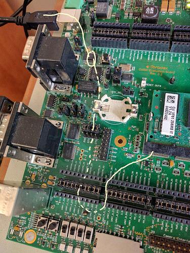
Yeah, I had exactly one of those (from FTDI). In my case it is a USB-232 to CMOS-TTL serial adapter, where the USB is connected to my development machine, and the LEDs where displaying correctly… Which seemed that the problem was on the target. This is my serial/UART setup for UART_A. Maybe this helps someone!
I’m afraid that I have to unaccept the question since the problem has reappeared and what I’ve explained above does not work.
I’m back at square one, but I’ve tried with 2 different USB-Serial adapters with the same result. LEDs in the USB adapter show that data is outputed but cat /proc/tty/driver/fsl-lpuart tells that no bytes are received…
Ok, I think this is the good one :')
First of all, I was using the Colibri Evaluation Board V3.1. After making an small serial echo program, I shorted Tx-Rx and finally the board started receiving! It got me wondering that, somehow, the USB Tx was not working at supposed.
After checking the voltages, it confirmed my suspicions: While with Tx and Rx shorted, the voltage was over 2.5V (TTL/CMOS), the USB was around 0.8V when connected to the board (3.3V while not connected).
After isolating the problem I tried in the Viola board, to find out that there it worked perfectly with both voltages over 2.5V. I haven’t check the Colibri Evaluation Board schematic thoroughly but it seems that there is something in the DCD and the DSR pins that lowers the voltage (Low value load resistor?) making the CMOS not high enough to work.
I don’t know if it’s intended but at least it should be worth looking 
TL;DR: RX is not working in UARTD (UART_A DCD and DSR) as supposed (at least with a 232-USB adapter) in the Colibri Evaluation Board. Try in the Viola Board (Iris doesn’t have direct output for those pins).
Thanks for the idea, that worked! However I’m using the Colibri Board V3.1 so I don’t have the JP17/19. This is my setup that got it working: Please notice the jumper removed.
Thanks again, Álvaro.
Note that the evaluation board has a FTDI on-board (X27, close to the power input). According to the pictures you took, the FTDI is not powered externally, but it is connected through the jumpers. Maybe its a backfeeding issue?
Either remove the jumper between X10/X12, or JP17/19 which connect to the FTDI. Or better, make use of the FTDI, and connect X27 to your development host.
