U-boot space LCD display not working

Hello,
I am working with a imx6ull-colibri som.
BSP version 5.6.0
I have a 800x480 lvds display connected.
I have my custom yocto image that show a kernel splash screen and a user space splash screen.
The resolution is configured by vidargs u-boot variable vidargs=video=mxsfb:800x480M-16@60 and in dts file:

			timing_wvga: 800x480 {
				clock-frequency = <33260000>;
				hactive = <800>;
				vactive = <480>;
				hback-porch = <216>;
				hfront-porch = <40>;
				vback-porch = <35>;
				vfront-porch = <10>;
				hsync-len = <128>;
				vsync-len = <2>;
				de-active = <1>;
				hsync-active = <0>;
				vsync-active = <0>;
				pixelclk-active = <0>;
			};

I read in documentation that if we have setted vidargs u-boot variable the dts settings has not take effect.
In kernel ans user space the display is working fine, shows kernel logo and then splashscreen user space and the my personal application.
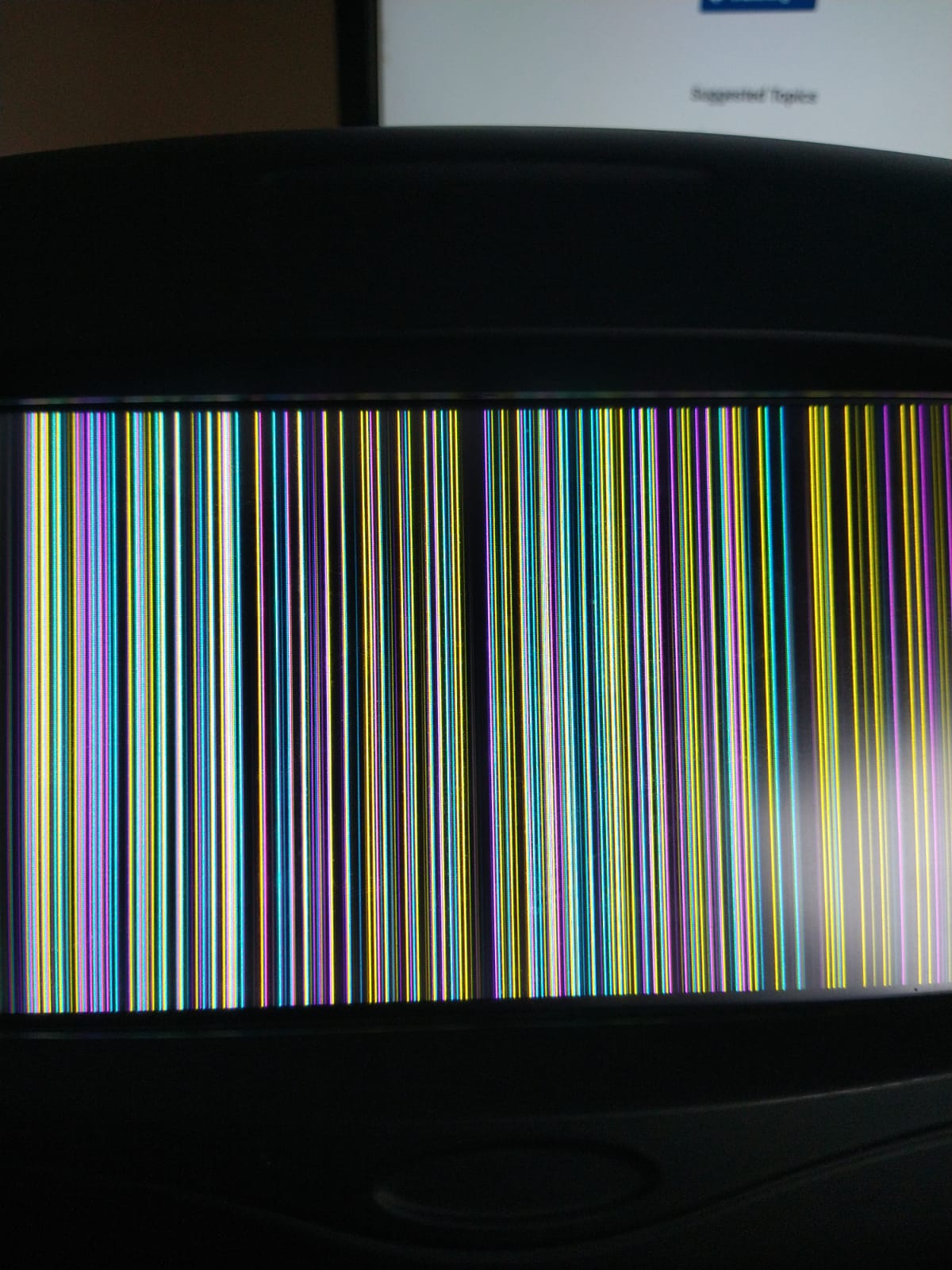
My problem is in u-boot space, when the u-boot is running the diplay is showing a bad image and is not showing u-boot logo.
I have a ttl diplay too and shows the u-booy logo but in a different resolution with a parte of the image cut.
Aneway, I need to use a LVDS display.
I think that the problem is that in u-boot space the display sittings are different that in kernel space.
I try to change u-boot variable videomode but there is not change.
What is the way to set display configuration in u-boot space?

Please note that the Colibri imx6ull module does not have an LVDS interface, so the issue most likely lies in the configuration of your Parallel RGB to LVDS converter. To provide further assistance, we need details about your LVDS converter and the LVDS display you are using.
It would also be helpful if you could describe the aforementioned “bad image” or, even better, share a picture.

Yes, heres is the image

FT070-SZG4WN00WVLD16(TS4)+( 7 inch 800x480 ,LVDS,1000nits) (1).pdf (2.1 MB)
I attached the LVDS datasheet.
We are using the same parallel rgb to lvds converter that Colibri evaluation board v3: DS90C363BMT/NOPB
The same problem we have in Colibri eval board v3.

Why in kernel space and user space is this working and not for u-boot?

The PWRDWN pin of DS90C363BMT/NOPB is connected to BL_ON pin, and this pin has a fisical 10 k pull up resistor connected to 3.3v. and this pin is put in 1 in setup_lcd() uboot function.

Most likely due to wrong resolution and pixel clock frequency used by U-Boot.

Yes I think the same. How can I configure resolution and pixel clock frecuency in u-boot?
Is with videomode=video=ctfb:x:800y:480,depth:18,pclk:39722,le:48,ri:16,up:33,lo:10,hs:96,vs:2,sync:0,vmode:0
?

Yes, you can set display parameters using the vidomode variable, but this will only take effect after the Linux kernel startup. Therefore, it doesn’t work during the U_boot stage. To change display parameters while only U_boot is running, you can modify the setup_lcd() function in U_boot to set the required parameters. Please refer to the iMX6ULL reference manual for details

Ah ok, I thought that videomode sets display parameters in u-boot.
I think that for default in u-boot the display is configured with a 640x480 resolution but I cannot find the way to set a different resolution.
setup_lcd() only turns on backlight, I made my changes here because I change pwm an bl_on backlight pins.
I am going to read reference manual to get with the way to change display parameters in u-boot.

Which api do I have to use to set display timmings?
I have exactly the same issue that this and reading differents posts It is clear that is a recurrent issue.
Here said that display support in U-BOOT starting was removed.
In concret wich api is used to set display timings?
Looking in u-boot source I found video.h, It seems that I have to use his one am I correct?

Ok, as we thought and as @alex.tx said I have to set display parameters in u-boot.
Looking for information I found Post
In u-boot I added:

#define LCD_PAD_CTRL    (PAD_CTL_HYS | PAD_CTL_PUS_100K_UP | \
		PAD_CTL_DSE_48ohm)

static iomux_v3_cfg_t const lcd_pads[] = {
	MX6_PAD_LCD_CLK__LCDIF_CLK		| MUX_PAD_CTRL(LCD_PAD_CTRL),
	MX6_PAD_LCD_ENABLE__LCDIF_ENABLE	| MUX_PAD_CTRL(LCD_PAD_CTRL),
	MX6_PAD_LCD_HSYNC__LCDIF_HSYNC		| MUX_PAD_CTRL(LCD_PAD_CTRL),
	MX6_PAD_LCD_VSYNC__LCDIF_VSYNC		| MUX_PAD_CTRL(LCD_PAD_CTRL),
	MX6_PAD_LCD_DATA00__LCDIF_DATA00	| MUX_PAD_CTRL(LCD_PAD_CTRL),
	MX6_PAD_LCD_DATA01__LCDIF_DATA01	| MUX_PAD_CTRL(LCD_PAD_CTRL),
	MX6_PAD_LCD_DATA02__LCDIF_DATA02	| MUX_PAD_CTRL(LCD_PAD_CTRL),
	MX6_PAD_LCD_DATA03__LCDIF_DATA03	| MUX_PAD_CTRL(LCD_PAD_CTRL),
	MX6_PAD_LCD_DATA04__LCDIF_DATA04	| MUX_PAD_CTRL(LCD_PAD_CTRL),
	MX6_PAD_LCD_DATA05__LCDIF_DATA05	| MUX_PAD_CTRL(LCD_PAD_CTRL),
	MX6_PAD_LCD_DATA06__LCDIF_DATA06	| MUX_PAD_CTRL(LCD_PAD_CTRL),
	MX6_PAD_LCD_DATA07__LCDIF_DATA07	| MUX_PAD_CTRL(LCD_PAD_CTRL),
	MX6_PAD_LCD_DATA08__LCDIF_DATA08	| MUX_PAD_CTRL(LCD_PAD_CTRL),
	MX6_PAD_LCD_DATA09__LCDIF_DATA09	| MUX_PAD_CTRL(LCD_PAD_CTRL),
	MX6_PAD_LCD_DATA10__LCDIF_DATA10	| MUX_PAD_CTRL(LCD_PAD_CTRL),
	MX6_PAD_LCD_DATA11__LCDIF_DATA11	| MUX_PAD_CTRL(LCD_PAD_CTRL),
	MX6_PAD_LCD_DATA12__LCDIF_DATA12	| MUX_PAD_CTRL(LCD_PAD_CTRL),
	MX6_PAD_LCD_DATA13__LCDIF_DATA13	| MUX_PAD_CTRL(LCD_PAD_CTRL),
	MX6_PAD_LCD_DATA14__LCDIF_DATA14	| MUX_PAD_CTRL(LCD_PAD_CTRL),
	MX6_PAD_LCD_DATA15__LCDIF_DATA15	| MUX_PAD_CTRL(LCD_PAD_CTRL),
	MX6_PAD_LCD_DATA16__LCDIF_DATA16	| MUX_PAD_CTRL(LCD_PAD_CTRL),
	MX6_PAD_LCD_DATA17__LCDIF_DATA17	| MUX_PAD_CTRL(LCD_PAD_CTRL),
};

Then

static int setup_lcd(void)
{
	printf("Setup lcd pads\n");

	imx_iomux_v3_setup_multiple_pads(lcd_pads, ARRAY_SIZE(lcd_pads));
	imx_iomux_v3_setup_multiple_pads(backlight_pads, ARRAY_SIZE(backlight_pads));

	/* Set BL_ON */
	gpio_request(GPIO_BL_ON, "BL_ON");
	gpio_direction_output(GPIO_BL_ON, 1);

	/* Set PWM<B> to full brightness (assuming inversed polarity) */
	gpio_request(GPIO_PWM_B, "PWM<B>");
	gpio_direction_output(GPIO_PWM_B, 1);

	return 0;
}

That only configure lcd pins.

To set display timing is with

struct display_info_t const displays[] = {{
	.bus	= MX6UL_LCDIF1_BASE_ADDR,
	.addr	= 0,
	.pixfmt	= IPU_PIX_FMT_RGB666,
	.detect	= detect_default,
	.enable	= enable_rgb,
	.mode	= {
		.name           = "wvga-rgb",
		.refresh        = 60,
		.xres           = 800,
		.yres           = 480,
		.pixclock       = 30066,
		.left_margin    = 216,
		.right_margin   = 40,
		.upper_margin   = 35,
		.lower_margin   = 10,
		.hsync_len      = 128,
		.vsync_len      = 2,
		.sync           = 0,
		.vmode          = FB_VMODE_NONINTERLACED
} } };

This is used in api video.h and displays is setting in function int ipu_displays_init(void);
I added debug prints in video.c but It seems that is not executing this function.
I found config value CONFIG_VIDEO_IPUV3 but when I add It u-boot doesn’t compile.

HI @emmaperea ,

Thanks for the information!

What you are doing seems correct, one more point to make sure of is that the flag CONFIG_DM_VIDEO is enabled, can you confirm this?

The video was disabled on U-boot by default on this patch, you can just revert this enabling the config above to make it work again.

Best regards,
Daniel Morais

Hello @daniel_m.tx ,
Yes I have set the CONFIG_DM_VIDEO set.
I had success to config the display resoluction in u-boot with the u-boot dts arch/arm/dts/imx6ull-colibri-u-boot.dtsi
Setting display timings as follow:

 			timing_vga: 800x480 {
 				u-boot,dm-pre-reloc;
-				clock-frequency = <25175000>;
-				hactive = <640>;
+				clock-frequency = <33260000>;
+				hactive = <800>;
 				vactive = <480>;
-				hback-porch = <40>;
-				hfront-porch = <24>;
-				vback-porch = <32>;
-				vfront-porch = <11>;
-				hsync-len = <96>;
+				hback-porch = <216>;
+				hfront-porch = <40>;
+				vback-porch = <35>;
+				vfront-porch = <10>;
+				hsync-len = <128>;
 				vsync-len = <2>;
 
 				de-active = <1>;

This was the only way that I could set the my display timings.
However I still have an issue, the display starts on with the wrong config until execute the setup_lcd() function. I had to change bl_on pin and backlight pwm pin, the changes are:

 static iomux_v3_cfg_t const backlight_pads[] = {
 	/* Backlight On */
-	MX6_PAD_JTAG_TMS__GPIO1_IO11		| MUX_PAD_CTRL(NO_PAD_CTRL),
-	/* Backlight PWM<A> (multiplexed pin) */
-	MX6_PAD_NAND_WP_B__GPIO4_IO11		| MUX_PAD_CTRL(NO_PAD_CTRL),
+	
+	MX6_PAD_CSI_DATA07__GPIO4_IO28		| MUX_PAD_CTRL(NO_PAD_CTRL),
+	/* Backlight PWM<B> (multiplexed pin) */
+	MX6_PAD_NAND_DQS__GPIO4_IO16		| MUX_PAD_CTRL(NO_PAD_CTRL),
 };

Here seems that have the same issue that me.
How can I change pin configurations that the display starts off and turn on only in setup_lcd()?
Do I have to change pins config in u-boot dts?

Hi @emmaperea ,

Thanks for the detailed information.

By default the setup_lcd() function is executed on the board_init_late() function as you can see here, can you please try to move the function to the board_init() and verify if this works for you? The board_init() is one of the first functions executed on the boot time, so it may be enough to configure the pins here.

Best regards,
Daniel Morais

Hi @daniel_m.tx ,
thanks for you response.
Yes I already move the call to setup_lcd() to the board init function and still starting the display on. I think that the problem here is the default bl_on pin configuration that for some reason starts power on.

Hi @emmaperea ,

Thanks for the test!

Can you please try adding a Pull Down to these pins as described below?

diff --git a/board/toradex/colibri-imx6ull/colibri-imx6ull.c b/board/toradex/colibri-imx6ull/colibri-imx6ull.c
index bc11ab2272..ed9fde6ded 100644
--- a/board/toradex/colibri-imx6ull/colibri-imx6ull.c
+++ b/board/toradex/colibri-imx6ull/colibri-imx6ull.c
@@ -42,6 +42,10 @@ DECLARE_GLOBAL_DATA_PTR;
 
 #define NAND_PAD_READY0_CTRL (PAD_CTL_DSE_48ohm | PAD_CTL_PUS_22K_UP)
 
+#define WEAK_PULLDOWN  (PAD_CTL_PUS_100K_DOWN |                \
+       PAD_CTL_SPEED_MED | PAD_CTL_DSE_40ohm |                 \
+       PAD_CTL_HYS | PAD_CTL_SRE_SLOW)
+
 #define FLASH_DETECTION_CTRL (PAD_CTL_HYS | PAD_CTL_PUE)
 #define FLASH_DET_GPIO IMX_GPIO_NR(4, 1)
 static iomux_v3_cfg_t const flash_detection_pads[] = {
@@ -69,9 +73,9 @@ static void setup_gpmi_nand(void)
 #ifdef CONFIG_DM_VIDEO
 static iomux_v3_cfg_t const backlight_pads[] = {
        /* Backlight On */
-       MX6_PAD_JTAG_TMS__GPIO1_IO11            | MUX_PAD_CTRL(NO_PAD_CTRL),
-       /* Backlight PWM<A> (multiplexed pin) */
-       MX6_PAD_NAND_WP_B__GPIO4_IO11           | MUX_PAD_CTRL(NO_PAD_CTRL),
+       MX6_PAD_CSI_DATA07__GPIO4_IO28          | MUX_PAD_CTRL(WEAK_PULLDOWN),
+       /* Backlight PWM<B> (multiplexed pin) */
+       MX6_PAD_NAND_DQS__GPIO4_IO16            | MUX_PAD_CTRL(WEAK_PULLDOWN),
 };
 
 #define GPIO_BL_ON IMX_GPIO_NR(1, 11)

If this not works, I’d like you to try to add the Pull Down to the device tree directly changing here and here the PAD configuration. To verify the PAD configuration you want please check the Table 4-2 Pad Control Register from the Colibri iMX6ULL datasheet.

Please let me know if any of the above solutions work and if you need any further assistance.

Best regards,
Daniel Morais

Hi,
After some days reading documentation and making tests over colibri imx6ull som we couldn’t set default pins configuration.
Some pins such as Pin 59 PWM_A → imx6ull pwm4.out and pin 28 PWM_B → imx6ull pwm5.out starts with high state at init, then we change its state in board_init() u-boot function but when power on and pin take u.-boot configuration takes about 2 seconds.
Other pins starts with low level at init and we can change state in u-boot funcition, pins are: pin 30 PWM_C → imx6ull pwm6.out and pin 67 es el PWM_D → imx6ull pwm7.out, so changing pwm backlight to pin 67 starts with backlight off and power on when executes u-boot function.
Is that correct? thaere are some pins configuraction with differents init levels?

Hi @emmaperea ,

Sorry for the delay in answers, I was investigating it internally.

To make sure, even configuring the pins on the device tree, do these pins you commented on always come up with those signals?

Best regards,
Daniel Morais

Yes, I configured those pins in kernel device tree and u-boot device tree.

Hi @emmaperea ,

Thanks for your response and sorry for the delay in answering.

I will be doing some tests with this in the next few days, I will come back to you as soon as I have some results.

Best regards,
Daniel Morais

Hi @emmaperea ,

To change the initial state of the SODIMM 28 you may change the DCD table of the processor directly via U-Boot, you can do this by doing some modifications on the board/toradex/colibri-imx6ull/imximage.cfg file. For more information about DCD, please take a look at the topic 8.7.2 Device Configuration Data (DCD) of the iMX6ULL reference manual.

Below is a patch that applies all necessary changes:

diff --git a/board/toradex/colibri-imx6ull/colibri-imx6ull.c b/board/toradex/colibri-imx6ull/colibri-imx6ull.c
index bc11ab2272..c927b9cff0 100644
--- a/board/toradex/colibri-imx6ull/colibri-imx6ull.c
+++ b/board/toradex/colibri-imx6ull/colibri-imx6ull.c
@@ -42,10 +42,15 @@ DECLARE_GLOBAL_DATA_PTR;
 
 #define NAND_PAD_READY0_CTRL (PAD_CTL_DSE_48ohm | PAD_CTL_PUS_22K_UP)
 
+#define WEAK_PULLDOWN  (PAD_CTL_PUS_100K_DOWN |                \
+       PAD_CTL_SPEED_MED | PAD_CTL_DSE_40ohm |                 \
+       PAD_CTL_HYS | PAD_CTL_SRE_SLOW)
+
 #define FLASH_DETECTION_CTRL (PAD_CTL_HYS | PAD_CTL_PUE)
 #define FLASH_DET_GPIO IMX_GPIO_NR(4, 1)
 static iomux_v3_cfg_t const flash_detection_pads[] = {
        MX6_PAD_NAND_WE_B__GPIO4_IO01 | MUX_PAD_CTRL(FLASH_DETECTION_CTRL),
+       MX6_PAD_NAND_DQS__GPIO4_IO16 | MUX_PAD_CTRL(WEAK_PULLDOWN)
 };
 
 static bool is_emmc;
@@ -93,6 +98,17 @@ static int setup_lcd(void)
 }
 #endif
 
+#define GPIO_28 IMX_GPIO_NR(4, 16)
+
+static int setup_sodimm28_pin(void)
+{
+       /* Set SODIMM 28 */
+       gpio_request(GPIO_28, "GPIO_28");
+       gpio_direction_output(GPIO_28, 0);
+
+       return 0;
+}
+
 #ifdef CONFIG_FEC_MXC
 static int setup_fec(void)
 {
@@ -132,6 +148,8 @@ int board_init(void)
        is_emmc = gpio_get_value(FLASH_DET_GPIO);
        gpio_free(FLASH_DET_GPIO);
 
+       setup_sodimm28_pin();
+
 #ifdef CONFIG_FEC_MXC
        setup_fec();
 #endif
diff --git a/board/toradex/colibri-imx6ull/imximage.cfg b/board/toradex/colibri-imx6ull/imximage.cfg
index e162cff90f..fad82bf392 100644
--- a/board/toradex/colibri-imx6ull/imximage.cfg
+++ b/board/toradex/colibri-imx6ull/imximage.cfg
@@ -101,3 +101,6 @@ DATA 4 0x021B0818 0x00000227
 DATA 4 0x021B0004 0x0002556D
 DATA 4 0x021B0404 0x00011006
 DATA 4 0x021B001C 0x00000000
+/* NAND_DQS SODIMM_28 */
+DATA 4 0x020E01B8 0x00000005
+DATA 4 0x020E0444 0x00003000
\ No newline at end of file

For more information about the changes on the register 0x020E01B8, please take a look at the topic 32.6.94 SW_MUX_CTL_PAD_NAND_DQS SW MUX Control Register (IOMUXC_SW_MUX_CTL_PAD_NAND_DQS) of the iMX6ULL reference manual.

For more information about the changes on the register 0x020E0444, please take a look at the topic 32.6.240 SW_PAD_CTL_PAD_NAND_DQS SW PAD Control Register (IOMUXC_SW_PAD_CTL_PAD_NAND_DQS) of the iMX6ULL reference manual.

Best regards,
Daniel Morais

1 Like

Thanks daniel!