SPI Slave configuration on Apalis imx8qp devicetree setup

Hi,

We are trying to configure the SPI device on the Apalis imx8. Our setup consist of a (Custom) Apalis board we call “Core” and one of more Slave device’s we call “Hubs”. We connect the Core and Hubs using a Daisy chain configuration and want to configure one SPI bus on the Apalis board as Master and a 2nd one as a Slave device.

SP1 as a master and SP2 as a slave. In the devicetree both SPI buses are configured as Master if I understand correctly . To set the Apalis SPI2 as a slave device I adjusted the devicetree files as follow:

file:imx8-aplais-ixora-custom.dtsi →

/* Apalis SPI2 */
&lpspi2 {
	spi-slave;
	status = "okay";
};

file :imx8-apalis-v1.1.dtsi →

/* Apalis SPI2 */
&lpspi2 {
	pinctrl-names = "default";
	pinctrl-0 = <&pinctrl_lpspi2>;
	#address-cells = <1>;
	#size-cells = <0>;
	cs-gpios = <&lsio_gpio3 10 GPIO_ACTIVE_LOW>;

	spidev1: slave@0 {
		compatible = "toradex,evalspi";
		reg = <0>;
		spi-max-frequency = <4000000>;
	};
};

After flashing the newly created image I was able to Init and set both SPI devices (Using the SPiTestUtility.c with spidev driver). After sending data the spi master stops responding.

Without devicetree adjustment I could send data of the SPI Master (SPI1) but not receive it on SPI2.

Did I configure the devicetree correctly ?
In Linux two spi device’s are available /dev/spidev0.0 (master) and dev/spidev1.0 (slave)

Connection Layout (pin config default):

SPI1_CLK  :  OUT CLK
SPI1_MOSI: OUT DATA
SP1_CS      : OUT SS

SPI2_MOSI: IN DATA
SP2_CS     :  IN_CS
SPI2_CLK :  IN_CLK

Test Logging (Visual Studio Code):

  • Init spi 1 *
    spi mode: 0x1
    bits per word: 8
  • Init spi 2 *
    spi mode: 0x1
    bits per word: 8
    speed set to: 300000
    set bits per burst to: 8

System:
Module : Toradex Apalis iMX8QP
Linux with TorizonCore 5.7.0 docker containers

Note: core and hub worked with an iMX6 Module and dedicated spi_driver.

Hello @wjanssen ,
Pleas have a look at this thread in the NXP community, it might help.

Best regards,
Josep

Hi Josep,

I looked the information on the NXP site however the links to the examples provided are broken. Can you supply an Example or an updated link that works ?

I was able to get a new link to the SCFWKIT but that did not help me much
scfwkit :
https://www.nxp.com/webapp/sps/download/license.jsp?colCode=L4.14.98_2.0.0_SCFWKIT-1.2

Greetings,
Willem

Hello @wjanssen ,
We have also found this one :

Please note that all the links to codeaurora.com are broken (https://bye.codeaurora.org) You might try to find the examples on NXP’s Github (NXP · GitHub).

Best regards,
Josep

Hi @wjanssen !

Do you have an update about this thread? Was your issue solved? :slight_smile:

Best regards,

Unfortunately we are still struggling with this. Using a daisy chain setup is not widely used. We were not able to find a good example. In more detail the data in is connected on the MOSI port in the daisy chain setup which is different when using regular SPI.

Hi @wjanssen !

I would like to ask you to try the following:

  • Add spi-slave to &lpspi2 (as you have already done)
  • Remove/Delete the cs-gpios property from &lpspi2
    • You need to add /delete-property/ cs-gpios; to the node.
      • Important: It can’t be done in a device tree overlay
  • Change the mux of the pin IMX8QM_SPI2_CS0 from LSIO_GPIO3_IO10 to DMA_SPI2_CS0
    • You can change direcly the pinctrl_ecspi2 or create a new pinctrl set and assign it to the pinctrl-0 property of &lpspi2

This should be it for the device tree modification.

To test it, please refer to Tests:MSIOF-SPI-Slave - eLinux.org.

Let us know if this helps you :slight_smile:

Best regards,

Hi,

Thank you for your suggestions. I have added the /delete propertery/ cs-gpios to the &lpspi2 and changed the mux of the pin in the devicetree. The result was that the slave device was able to receive bytes but the spimaster locks up after sending data.
Next I updated the SPI master &lpspi0 by adding the /delete-property cgpios and
changing the mux of the pin IMX8QM_SPI0_CS0 from IMX8QM_SPI0_CS0_LSIO_GPIO3_IO05 to
DMA_SPI0_CS0. Now the SPI Master was able to send data successfully but as soon as I tried to retrieve a message from the spi slave the slave device blocks. Here the output from SPITester on the last change (1st the spi master, then the spi slave on spidev1.0) :

root@f99f75e4e81a:/ProgramLogic/bin# ./SPITest -v
spi mode: 0x0
bits per word: 8
max speed: 500000 Hz (500 kHz)
TX | 00 00 00 80 00 01 00 00 00 00 00 00 80 00 02 55 AA CC __ __ __ __ __ __ __ __ __ __ __ __ __ __ |…U…|
RX | 00 00 00 00 00 00 00 00 00 00 00 00 00 00 00 00 00 00 __ __ __ __ __ __ __ __ __ __ __ __ __ __ |…|
root@f99f75e4e81a:/ProgramLogic/bin# ./SPITest -v -D /dev/spidev1.0
spi mode: 0x0
bits per word: 8
max speed: 500000 Hz (500 kHz)

Afterwards dmseg shows the following output:
[11316.764060] spidev spi1.0: SPI transfer failed: -4
[11316.768904] spi_slave spi1: failed to transfer one message from queue

Greetings,
Willem

Hi @wjanssen !

Are you sure you should remove the cs-gpios property from the master SPI? AFAIK, it should be there, so the driver can use the CS pins.

A reference I found about i.MX8QM and SPI slave: imx8qm-lpddr4-val-lpspi-slave.dts « freescale « dts « boot « arm64 « arch - linux-toradex.git - Linux kernel for Apalis, Colibri and Verdin modules

But, as you are using daisy chain, I do not have information if the driver actually supports this topology (also, I am not sure whether this topology needs driver support or not - currently my guess is that it does).

Best regards,

Hi,

Good point. I added the cs-gpios to the master SPI again and tested it. In our case it did not make any difference. It could be that the driver does not fully support our setup. One single master or a single slave SPI device seems to work but not combined in one solution.

Hi @wjanssen !

Do you mean that if you connect SPI1 as master directly to SPI2 as slave it doesn’t work?

Or you meant that having more than one slave (in daisy chain) doesn’t work?

Or something else?

Best regards,

Hi @wjanssen!

Did you have time to go through the questions above?

An important remark: the slave must have its buffer defined with data before being called (e.g. with spidev). So you can’t define the answer to a message after you received it.


Also, could you please share how you did the setup on Apalis iMX6 to use the daisy chain on SPI? This could help us with some pointers. Which BSP version you used in Apalis iMX6? And was it upstream or downstream?

Best regards,

What I mean that if you only configure

  • one SPI device (SPI 1) configured as a Master it works.

  • one SPI device configured as a Slave it can receive data

  • two SPI devices on the board one configured as Slave, both initialed ok, but as soon as we send a message from the Master it the SPI bus blocks.

For the imx6 we directly write to the SPI registers (from user space). We recently got it working on Apalis-imx6 with TorizonCore

  • version:TorizonCore Upstream 5.7.0-devel-20220530110134+build.0 (dunfell)

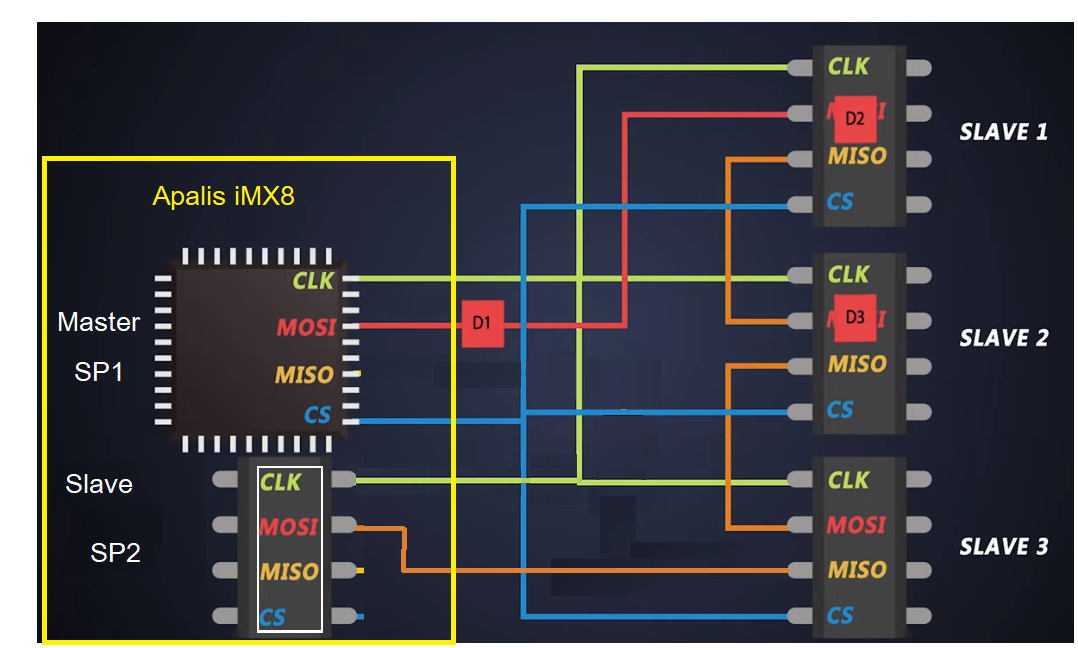
To give a little more insight. This is how it looks

SPI register pointers

unsigned int *SPI1_Register_Array[10];
unsigned int *SPI2_Register_Array[10];
unsigned int *GPIO5_pointer[8];

Init SPI1

	int  mem_fd;
	void *spi_map = 0;
	void *CCGR_map = 0;
	void *IOMUX_map = 0;
	void *GPIO_map = 0;

	unsigned int *CCGR_pointer = 0;
	unsigned int *IOMUX_pointer = 0;

	signed int temp;

	//Gain access to IOMUX register to set correct function
	if ((mem_fd = open("/dev/mem", O_RDWR|O_SYNC) ) < 0)// open: /dev/mem
	{
		printf("can't open /dev/mem \n");
		return -1;
	}
	IOMUX_map = mmap(NULL,0x0948,PROT_READ|PROT_WRITE,MAP_SHARED,mem_fd,0x20E0000);
	if (IOMUX_map == MAP_FAILED)
	{
		printf("mmap error\n");//errno also set!
		return -1;
	}

	IOMUX_pointer = IOMUX_map + 0x0274;
	*IOMUX_pointer = 0x00000005; //Set SPI1 to GPIO, we do manually set it
	IOMUX_pointer = IOMUX_map + 0x08F8;
	*IOMUX_pointer = 0x00000002; //Selecting alt 3 mode
	close(mem_fd);
	munmap(IOMUX_pointer,0x0948);

	//Gain access to IOMUX register to set correct function
	if ((mem_fd = open("/dev/mem", O_RDWR|O_SYNC) ) < 0)// open: /dev/mem
	{
		printf("can't open /dev/mem \n");
		return -1;
	}
	GPIO_map = mmap(NULL,0x0948,PROT_READ|PROT_WRITE,MAP_SHARED,mem_fd,0x20AC000);
	if (GPIO_map == MAP_FAILED)
	{
		printf("mmap error\n");//errno also set!
		return -1;
	}

	GPIO5_pointer[0] = GPIO_map + 0x0;
	temp = *GPIO5_pointer[0];
	temp |= 1 << 25;
	*GPIO5_pointer[0] = temp;//0x00000002; //Selecting alt 3 mode

	GPIO5_pointer[1] = GPIO_map + 0x4;
	temp = *GPIO5_pointer[1];
	temp |= 1 << 25;// set output0x00000005; //Set SPI1 to GPIO, we do manually set it
	*GPIO5_pointer[1] = temp;
	close(mem_fd);


	//Gain access to clock registers to be able to enable the SPI clock
	if ((mem_fd = open("/dev/mem", O_RDWR|O_SYNC) ) < 0)// open: /dev/mem
	{
		printf("can't open /dev/mem \n");
		return -1;
	}
	CCGR_map = mmap(NULL,0x4088,PROT_READ|PROT_WRITE,MAP_SHARED,mem_fd,0x020C4000);
	if (CCGR_map == MAP_FAILED)
	{
		printf("mmap error\n");//errno also set!
		return -1;
	}
	CCGR_pointer = CCGR_map + 0x6C ;
	*CCGR_pointer |= 0x00000005; //Enable SPI1 & SPI2 clock
	close(mem_fd);
	munmap(CCGR_pointer,4);

	//Gain access to the SPI registers to be able to initialize and use SPI
	if ((mem_fd = open("/dev/mem", O_RDWR|O_SYNC) ) < 0)// open: /dev/mem
	{
		printf("can't open /dev/mem \n");
		return -1;
	}
	spi_map = mmap(NULL,4,PROT_READ|PROT_WRITE,MAP_SHARED,mem_fd,0x02008000);
	if (spi_map == MAP_FAILED)
	{
		printf("mmap error\n");//errno also set!
		return -1;
	}
	SPI1_Register_Array[0] = spi_map + 0x00;// Always use volatile pointer!
	SPI1_Register_Array[1] = spi_map + 0x04;
	SPI1_Register_Array[2] = spi_map + 0x08;
	SPI1_Register_Array[3] = spi_map + 0x0C;
	SPI1_Register_Array[4] = spi_map + 0x10;
	SPI1_Register_Array[5] = spi_map + 0x14;
	SPI1_Register_Array[6] = spi_map + 0x18;
	SPI1_Register_Array[7] = spi_map + 0x1C;
	SPI1_Register_Array[8] = spi_map + 0x20;
	SPI1_Register_Array[9] = spi_map + 0x40;
	*SPI1_Register_Array[2] = 0x007050F1;
	//BURST_LENGTH = 8 -> a burst contains 8 bits
	//CHANNEL_SELECT = 0 -> SS0 will be used
	//DRCTL = 0 -> SPI_RDY don't care,
	//PRE_DEVIDER = 5 -> Root is 60 MHz, so devide by 6 this will result in 10 MHz
	//POST_DEVIDER = 0 -> Root is PRE_DEVIDER, so devide by 0 this will in a FINAL ~10 kHz CLK
	//CHANNEL_MODE[0] = F -> Make this the master, all other slaves
	//SMC = 0 -> Start a burst when XCH bit is set
	//XCH = 0 -> Dont start a burst (is only needed in the transmission function)
	//HT = 0 -> Disable HT mode (is also not supported)
	//EN = 1 -> Enable the SPI2
	*SPI1_Register_Array[3] = 0x00000F0F;
	//HT_LENGTH = 0 -> Is not supported
	//SCLK_CTL[0] = 0 -> Stay low
	//DATA_CTL[0] = 0 -> Stay high
	//SS_POL[0] = 0 -> Active low
	//SS_CTL[0] = 1 -> for master operation: Only one SPI burst will be send (to empty TXFIFO use 1)
	//SCLK_POL[0] = 0 -> Active high polarity
	//SCLK_PHA[0] = 1 -> 0 Phase 0 operation
	*SPI1_Register_Array[4] = 0x00000000; //Disable all interupt sources
	*SPI1_Register_Array[5] = 0x00000000; //Disable DMA for TXFIFO and RXFIFO
	*SPI1_Register_Array[6] = 0x000000C0; //Clear status register by writing 1
	*SPI1_Register_Array[7] = 0x00000000; //No additional wait delays
	*SPI1_Register_Array[8] = 0x00000000; //Disable Loop Back Control (LBC)
	close(mem_fd);

SPI1 Write

	unsigned int fifo_free = FIFO_SIZE - (*SPI1_Register_Array[8] & 0xFF);
	signed int CurrentBitSize;

	bit_size -= 1;

	if((bit_size / 32) <= fifo_free)
	{
		for(CurrentBitSize = bit_size; CurrentBitSize > 0; CurrentBitSize -= 8)
		{
			*SPI1_Register_Array[1] = (data[CurrentBitSize/32]>>(((CurrentBitSize-7)%32)));// & 0x000000FF;
		}
		return FIFO_SIZE - (*SPI1_Register_Array[8] & 0xFF);
	}
	else
		return fifo_free - (bit_size / 32);

SP1 Send data stored

signed int temp;

	temp = *GPIO5_pointer[0];
	temp &= ~(1 << 25);
	*GPIO5_pointer[0] = temp;//0x00000002; //Selecting alt 3 mode

	while((*SPI1_Register_Array[8] & 0xFF) != 0)
	{
		*SPI1_Register_Array[2] |= 0x04;	//Enable 32 bit transmission
		while ((*SPI1_Register_Array[2] & 0x4) >> 2)
		{
			usleep(1);
		}
	}

	temp = *GPIO5_pointer[0];
	temp |= 1 << 25;
	*GPIO5_pointer[0] = temp;//0x00000002; //Selecting alt 3 mode
}

SPI2 Init (slave)

	int  mem_fd;
	void *spi_map = 0;
	void *IOMUX_map = 0;
	unsigned int *IOMUX_pointer = 0;

	//Gain access to IOMUX register to set correct function
	if ((mem_fd = open("/dev/mem", O_RDWR|O_SYNC) ) < 0)// open: /dev/mem
	{
		printf("can't open /dev/mem \n");
		return -1;
	}
	IOMUX_map = mmap(NULL,0x0948,PROT_READ|PROT_WRITE,MAP_SHARED,mem_fd,0x20E0000);
	if (IOMUX_map == MAP_FAILED)
	{
		printf("mmap error\n");//errno also set!
		return -1;
	}
	IOMUX_pointer = IOMUX_map + 0x0104;
	*IOMUX_pointer = 0x00000002; //Set SPI1 to SS function
	close(mem_fd);
	munmap(IOMUX_pointer,0x0948);

	//Gain access to the SPI registers to be able to initialize and use SPI
	if ((mem_fd = open("/dev/mem", O_RDWR|O_SYNC) ) < 0)// open: /dev/mem
	{
		printf("can't open /dev/mem \n");
		return -1;
	}
	spi_map = mmap(NULL,4,PROT_READ|PROT_WRITE,MAP_SHARED,mem_fd,0x0200C000);
	if (spi_map == MAP_FAILED)
	{
		printf("mmap error\n");//errno also set!
		return -1;
	}
	SPI2_Register_Array[0] = spi_map + 0x00;// Always use volatile pointer!
	SPI2_Register_Array[1] = spi_map + 0x04;
	SPI2_Register_Array[2] = spi_map + 0x08;
	SPI2_Register_Array[3] = spi_map + 0x0C;
	SPI2_Register_Array[4] = spi_map + 0x10;
	SPI2_Register_Array[5] = spi_map + 0x14;
	SPI2_Register_Array[6] = spi_map + 0x18;
	SPI2_Register_Array[7] = spi_map + 0x1C;
	SPI2_Register_Array[8] = spi_map + 0x20;
	SPI2_Register_Array[9] = spi_map + 0x40;
	*SPI2_Register_Array[2] = 0x00705001;//0x00705001 for slave
	if(*SPI2_Register_Array[2] == 0x00705001)
		printf("SPI2 Control Register is correctly set.\r\n");
	//BURST_LENGTH = 8 -> a burst contains 8 bits
	//CHANNEL_SELECT = 0 -> SS0 will be used
	//DRCTL = 0 -> SPI_RDY don't care,
	//PRE_DEVIDER = 5 -> Root is 60 MHz, so devide by 6 this will result in 10 MHz
	//POST_DEVIDER = 0 -> Root is PRE_DEVIDER, so devide by 0 this will in a FINAL ~10 kHz CLK
	//CHANNEL_MODE[0] = 0 -> All slave
	//SMC = 0 -> Start a burst when XCH bit is set
	//XCH = 0 -> Dont start a burst (is only needed in the transmission function)
	//HT = 0 -> Disable HT mode (is also not supported)
	//EN = 1 -> Enable the SPI2
	*SPI2_Register_Array[3] = 0x00000F0F;//for slave 0x00000F00
	if(*SPI2_Register_Array[3] == 0x00000F0F)
			printf("SPI2 Config Register is correctly set.\r\n");
	//HT_LENGTH = 0 -> Is not supported
	//SCLK_CTL[0] = 0 -> Stay low
	//DATA_CTL[0] = 0 -> Stay high
	//SS_POL[0] = 0 -> Active low
	//SS_CTL[0] = F -> for master operation: Only one SPI burst will be send (to empty TXFIFO use 1)
	//SCLK_POL[0] = 0 -> Active high polarity
	//SCLK_PHA[0] = 0 -> 0 Phase 0 operation
	*SPI2_Register_Array[4] = 0x00000000; //Disable all interupt sources
	*SPI2_Register_Array[5] = 0x00000000; //Disable DMA for TXFIFO and RXFIFO
	*SPI2_Register_Array[7] = 0x00000000; //No additional wait delays
	*SPI2_Register_Array[8] = 0x00000000; //Disable Loop Back Control (LBC)
	close(mem_fd);
	return 0;

SPI2 read

	unsigned int RXCNT = (*SPI2_Register_Array[8] & 0xFF00) >> 8;
	unsigned int i;
	unsigned int RXDATA;

	//printf("STATREG SPI1 = %x. / STATREG SPI2  = %X\r",*SPI1_Register_Array[6], *SPI2_Register_Array[6]);

	//printf("RXCNT = %i.\r",RXCNT);
	for(i = 0; i < RXCNT; i++)
	{
		RXDATA = *SPI2_Register_Array[0];
		read_data_array[i] = RXDATA;
		//printf("RX FIFO = %X.\r",RXDATA);
	}
	return RXCNT;

Because of different Architecture of the iMX8 it is no longer possible to directly write to these registers as far as I understood from reading the iMX8 documentation.

Hm, what for are you using slave SPI? It is clearly application for single master SPI. Master SPI is a node, which emits SPI clock. I would understand if you had some external master SPI MCU, but it is your node, which initiates transfer and drives SPI CLK! Daisy chain like this isn’t something unusual. Think about it as single SLAVE N node from your picture, but having 3 times more data bits than a single slave node from your picture. It is 100% the same. No need to send data from one SPI instance and receive data on another SPI instance configured as slave. Single SPI instance is enough.
Your weird imx6 SPI Rx/Tx routines are wrong. I mean not clever /dev/mem access and lack of readable defines, but how do you read and write to SPI data registers. You should always check data is available before reading from data register, as well check FIFO isn’t full prior to writing it. Without such checks it may work, but as well may break at different CPU load.

Hi,

I agree that the imx6 routines are not very readable, it seems that the data is not checked for availability so we should check that. Unfortunately the developer who made these routines is no longer available and I do not have all the details.

In our setup we have up to 16 slave units connected at 1st, optionally we may want to extend this to 32. The distance between master and slave units can be 2 to 3 meters. To connect these units we use differential signaling. Differentiation gives a delay of 47 ns per unit meaning 1.5 uS for 32 units. This is the reason why the choice is made to add a slave unit to our Core device to avoid clock shifting and enabling to use high clock speed.

Hi

Then your picture doesn’t reflect clock and data delay lines. Do you pass your SPI clock through circuits with the same delay as SPI data? It is unusual. Data enters some slave IC, exits slave IC. And clock? Delay should be the same or clock low enough to make data delay irrelevant. It would be expensive to mach SPI data delay with SPI clock delay. The simplest is to just reduce SPI clock, and … you get application for single master SPI. Clock is too low? You may try changing SPI mode and sample data at “wrong” edge. If delay is really high, you would sample it right. Clock delay to the last node should match data delay anyway, else again, reduce SPI clock.
2-3m and 16 nodes isn’t a lot at all. Just a joke for CAN(FD) or RS485.