Hello,
I am using the “/dev/spidev0.0” driver and the corresponding pins on the x27 header to connect to a microcontroller which implements SPI slave.
Spidev is set to 6 MHz and spimode 0, 32bits data width. The slave is configured correspondingly.
Then I transmit/receive 8 uint32’s to/from the slave device.
In the debugger of the slave device, I can see the data sent from the Apalis TK1 master is all correct.
But the data received on the TK1 from the slave is wrong - a repeatable pattern.
The array in the write buffer of the slave contains numbers ascending from 0x50 to 0x57.
What the master receives instead is:
{0x28, 0x28, 0x80000029, 0x29, 0x8000002a, 0x2a, 0x8000002b, 0x2b}
You can see that there’s some upcounting in those values, and it’s basically the integer half of the expected value, and sometimes the MSB is set additionally.
Since SPI HW configuration is always for both directions (same on the slave implementation), and one direction works, there should be no configuration error.
The code doing the transfer is dead simple, nothing secial going on:
bool SpiDev::Transfer(unsigned char* send, unsigned char* receive, int length)
{
    struct spi_ioc_transfer transfer;
    memset(&transfer,0,sizeof(transfer));
    transfer.tx_buf = (unsigned long) send;
    transfer.rx_buf = (unsigned long) receive;
    transfer.len = length;
    transfer.speed_hz = m_speedHz;
    transfer.bits_per_word = m_bitWidth;
    transfer.delay_usecs = 0;
    int status = ioctl( m_fileId, SPI_IOC_MESSAGE(1), &transfer );
    if (status < 0)
 . . .
All that’s done outside of that is passing two u32 arrays of same size in, and after that, looping over them and printf()'ing the contents.
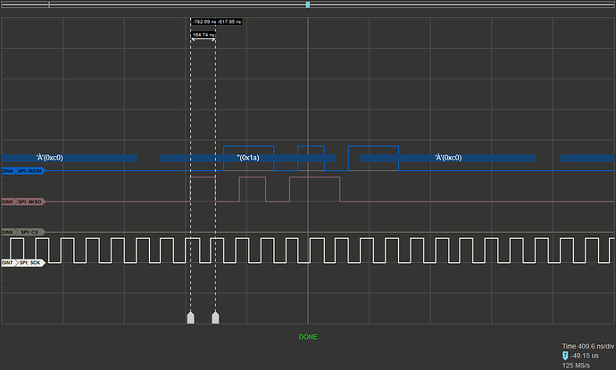
Also, I have a logic analyzer hooked up to this. While the analyzer for some reason decodes only the bytes on the MOSI line, not MISO (because it can’t, or won’t?) looking at the MISO line and the “hi” vs “lo” signal patterns, they do match the up-counted values of 0x50…0x57 as in bit patterns, and roughly the position with regards to the MOSI bytes, although it looks like there is some slight phase shift (don’t know if that’s normal. Some of it is due to sampling 6MHz pulse with 125Mhz, but not all of it, e.g. it’s 1/7 period vs.expected 1/20 period).
Does anyone have an idea of what could cause such a weird effect?
