Hi
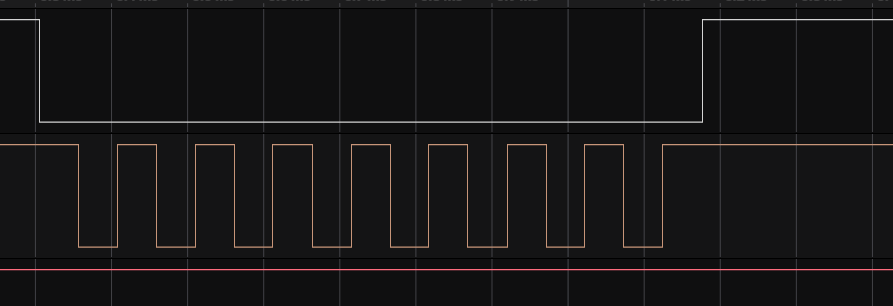
I am using “/dev/spidev1.0” for communicating with the ADC. The initial configuration is below and is successfull. I am using the ioctl functions to send message. When i send SPI message i see that the CS is pulled low for short duration equalent to single clock pulse and pulled back high.Due to this the clock lines also has single pulse. The device tree SPI 's max frequency is 10MHz and i am configuring for 5Mhz.
spi = new spi_interface();
spi->setMode(SPI_MODE_3);
spi->setSpeed(5000000);
Need help to troubleshoot this issue
Hi @VijayRichard,
welcome to our community! Feel free to ask any questions you might have.
In order to help you better with your scenario, could you please share more information with us?
- What is the exact issue that you are facing? Please, provide us with more information.
- What is the device that you are trying to communicate with?
- Could you please send us your
dmesg log?
Happy to help!
Hiago.
Hi,
Please Find the details below
- What is the exact issue that you are facing? Please, provide us with more information.
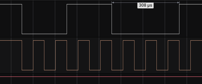
The Primary issue that i mentioned(single clock pulse) is resolved by doing a different SPI configuration sequence. But moving further, the current issue that i am facing is distorted MOSI signal.For various values of the txbuffer that i am sending, The MOSI data is incorrect.Attaching the same for your reference.
- What is the device that you are trying to communicate with?
I am trying to communicate with AD7928 which is an 8 channel ADC.I am using Dhalia pins 22,23,24,25 from the primary header.
- Could you please send us your
dmesg log?
Attaching the MOSI signal agaist the Clock. The data that i am sending is in the name of the file
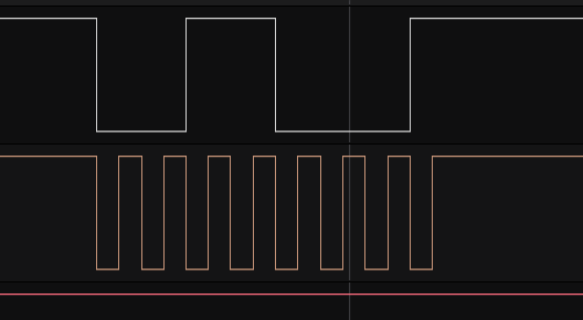
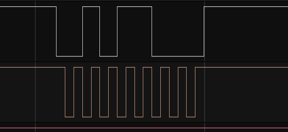
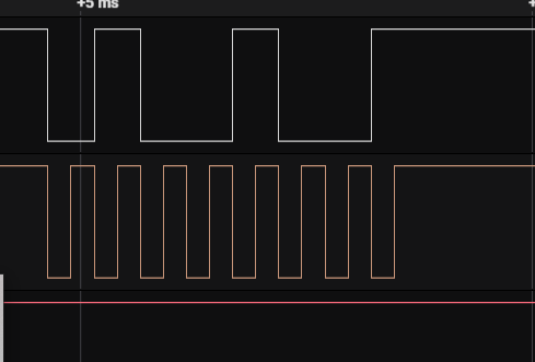
The data order in the image is 0x02,0x03,0x04,0x11,0x55
Hi @VijayRichard,
Thanks for the information!
One more question: can you send us the output of the command below?
(if you’re not using TorizonCore, please remove the “sudo” command)
sudo fw_printenv fdtfile
This way we can check if you are using the right device tree.
Also, have you done any changes to your device tree?
Best regards,
Hiago.
Hi,
I use Putty to connect with the Hardware and not able to run the command “fw_printenv fdtfile”.
I built the linux image using Ubuntu on Hyper-V.Flashed the image onto SD card and then use the SD card to bootup my Board using easy installer.
Is there any other way i can run the mentioned command?
Regards
Vijay Richard
Hi @VijayRichard,
You can go to the u-boot terminal (after you pressed the power on button on your module, keep pressing the space bar to access the u-boot command line), and then you can type:
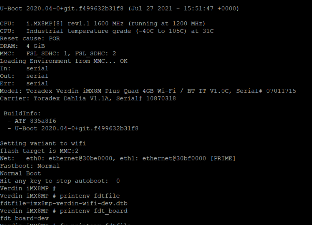
printenv fdtfile
printenv fdt_board
This will print which device tree is being loaded by the bootloader.
Best regards,
Hiago.
Hi,
Here is the command output
Hi @VijayRichard,
Thanks for the information!
As we can see, u-boot is loading the development board device tree, which is the default option. You are using a Dahlia board, so first let’s change to the right device tree file to check if this will solve your issue.
Please, in u-boot terminal, run these commands:
setenv fdt_board dahlia
saveenv
reset
This will set the right device tree and reboot your module.
Best regards,
Hiago.
Thanks Hiago, I will run these commands and then check the SPI message.
I will update you on Monday with the results.
1 Like