SPDIF recording frequency

Hello.

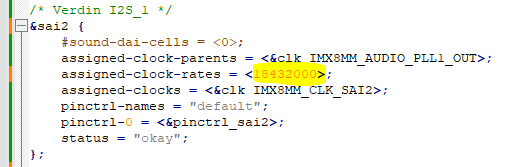
I have an ADC conected to the SAI5 (I2S_2) interface and I’m able to get samples from it using the s/pdif receiver driver up to 64 kHz, which needs roughly a 24 MHz clock, but need to record at 128 kHz. The SAI5 interface has been configured using the .dts files, with its clock configured at 49.152 MHz, as shown below:

&sai5 {
	#sound-dai-cells = <0>;
	assigned-clock-parents = <&clk IMX8MM_AUDIO_PLL1_OUT>;
	assigned-clocks = <&clk IMX8MM_CLK_SAI5>;
	assigned-clock-rates = <49152000>;
	pinctrl-names = "default";
	pinctrl-0 = <&pinctrl_sai5>;
	status = "okay";
};

The output of tail -10 /sys/kernel/debug/clk/clk_summary is

             audio_pll2_out           0        0        0   361267200          0     0  50000
    audio_pll1_ref_sel                0        0        0    24000000          0     0  50000
       audio_pll1                     0        0        0   393216000          0     0  50000
          audio_pll1_bypass           0        0        0   393216000          0     0  50000
             audio_pll1_out           0        0        0   393216000          0     0  50000
                sai5                  0        0        0    49152000          0     0  50000
                   sai5_root_clk       0        0        0    49152000          0     0  50000
                sai2                  0        0        0    24576000          0     0  50000
                   sai2_root_clk       0        0        0    24576000          0     0  50000
 osc_32k                              0        0        0       32768          0     0  50000

To record, I’m using the following command:

$ arecord -D hw:0,0 -V mono -vvv -c 8 -f S24_LE -r 64000

I believe the limitation might be coming from the s/pdif, can you please confirm if I can use the spdif driver to record at frequencies above 64 kHz?

I have the following boards and OS:
Verdin imx8m-mini
Verdin Development Board V1.1B
TorizonCore 5.7.0+build.17 (dunfell)

Best regards,

Hello @pato ,

Could you please tell us which ADC have you connected to your carrier board?

Best regards,
Josep

Hi @josep.tx.

Sure, it’s the ADS1278 from Texas Instruments.

HI, @pato,

you mentioned SPDIF as well just to clear any confusion can you share the schematic how you connected the ADC ?

Best Regards,

Matthias Gohlke

Hi @matthias.tx , sorry for the delay.

I don’t have the schematic, but the following table shows the connections:

ADS1278 Signal iMX8M Mini Function MUX
CLK/SCLK SODIMM 42 I2S_2_BCLK MX8MM_IOMUXC_SAI5_RXD2_SAI5_TX_BCLK
FSYNC SODIMM 44 I2S_2_SYNC MX8MM_IOMUXC_SAI5_RXD1_SAI5_TX_SYNC
DOUT1 SODIMM 48 I2S_2_D_IN MX8MM_IOMUXC_SAI5_RXD0_SAI5_RX_DATA0

Just to clarify, the CLK/SCLK from the ADC is driven using the I2S_2_BCLK (the bitclock) signal of the board, the FSYNC of the ADC with the SYNC signal and DOUT1 is the output of the ADC sent to the board as I2S_2_D_IN.

This is working for up to 64 kHz, so the connections are ok. Also, using a logic analyzer shows the correct output for both I2S_2_BCLK and I2S_2_SYNC, and as I2S_2_D_IN is the only input, there’s no need for the ADC to test the configuration.

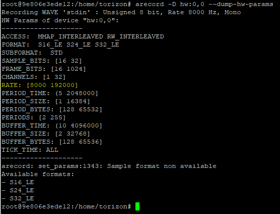
Running arecord with the --dump-hw-params shows that it should work up to 192 kHz.

Regards,

so what happens when you set it to higher freq?
do you have some OSC plots?

Best Regards,

Matthias Gohlke

Hi @matthias.tx ,

We have tested with several samplerates, and we get the following results:

  • Working frequencies: 8000 / 16000 / 32000 / 64000
    For these cases, correct values were measured at SODIMM 42 (BCLK) and 44 (SYNC), being them:
arecord RATE / BCLK / SYNC
8000 / 1536000 / 8000
16000 / 3072000 / 16000
32000 / 6144000 / 32000
64000 / 12288000 / 64000

RATE = SYNC, and we are recording 8 channels, 24-bit resolution, so BCLK = 24 * 8 * RATE
And also arecord command works properly, generating desired wav output files.

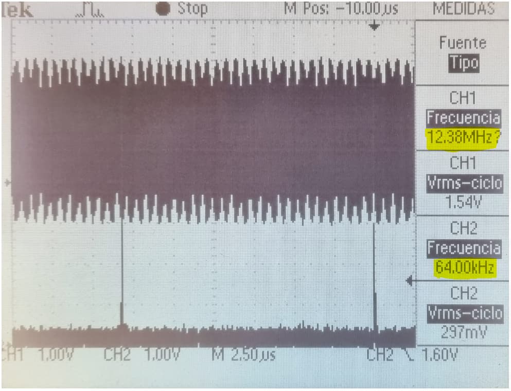
For example, using:
$ arecord -D hw:0,0 -r 64000 -V mono -vvv -c 8 -f S24_LE -t wav test_8ch-64ksps.wav -d 10
We measured the following signals: CH1=BCLK and CH2=SYNC (a little noisy, but it works)

Then, when we try higher frequencies, arecord command throws error, and no clk signals are generated.
Some examples:

$ arecord -D hw:0,0 -r 96000 -V mono -vvv -c 8 -f S24_LE -t wav test_8ch-96ksps.wav -d 10


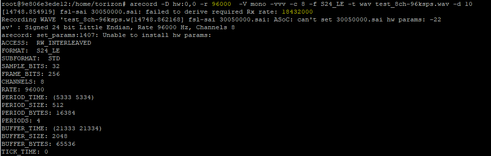
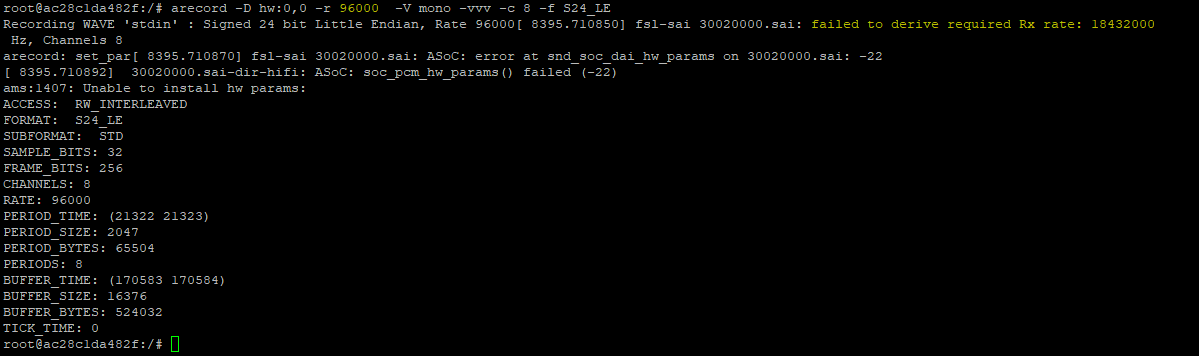
In this case: 24 * 8 * 96000 = 18432000, but is fails to generate that rate.
The same happens at 128000 and 192000, and also other standard rates like 44100 and 48000.

While asking for supported hardware parameters, it shows that 192000 should be supported.
image

Could be a limitation on SAI5 clock source?
Do you know if a higher frequency clok source could be selected to be used by SAI5?
Thanks in advance.

Best regards,
Alejandro

Hi @matthias.tx , @josep.tx

Has there been any avance with is issue? Is there anything else that I or @apanelli can do to help?

Thanks!

Hi @matthias.tx / @josep.tx ,

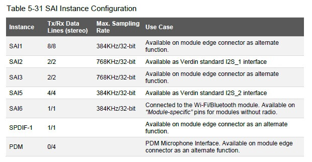
At Verdin iMX8MM datasheet we have seen that SAI5 max sampling rate is 384KHz/32-bit, that it is equivalent to a bit clock of 12.288.000Hz. This max bit clock in our case limits the sample rate to 64KHz because we are using 192-bit frames.
image

So we have disabled NAU8822 codec in Verdin DEV board, to allow using SAI2 with our ADC.
As shown in table, SAI2 should support bit clock frequencies up to 24.576.000Hz, allowing us to use 128KHz sampling rate. But then, we noticed that the driver does not support 128KHz.

So, we tried other standard sampling rates that are supported by the driver, like 88.2KHz and 96KHz, but we get the same error:


As you can see, it fails when it tries to obtain required BCLK.
The same happens when trying multiple frequencies of them, like 44.1KHz and 48KHz.

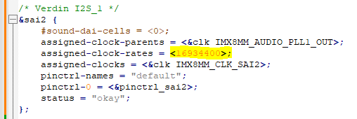
After that we tried to change assigned-clock-rates value at &sai2 node at dts, in order to set a value to match exactly the required bit clocks, but it seems it is not capable to generate those values.
When we use the following value for 44.1KHz and 88.2KHz, that should work with a BCLK of 16.934.400Hz:
image

It generates a 17.096.384Hz clock:

And the same happens while trying to generate 18.432.000Hz, to be used by 48KHz and 96KHz, it generates a 18.724.572Hz clock, that does not match.
image

What do you suggest to do to generate those values?

Best regards,
Alejandro

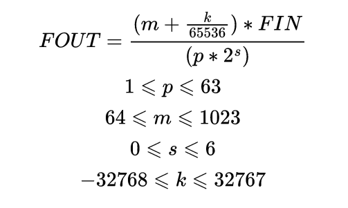
Is there a simple way to change audio_pll1_out or audio_pll2_out clock values?

I think that asigning a multiple value of 18432000Hz (96000x192) or 16934400Hz (88200x192) and then set this pllx as base of SAI2, it should be able to generate required rates.

Example: current clock value for audio_pll2_out is 361267200 Hz.
How can I change it to 387072000Hz?

Thanks in advance.
Best regards,
Alejandro

Hi @pato , @apanelli

Can you tell us which software are you using (BSP or TorizonCore)?
And which version are you using (5.7; 6;…)?

Best regards,
Larissa

Hi Larissa.

We are using TorizonCore, and have tried with version 5.7 and 6.2 (this was mentioned on the first post).

Best regards.

Hi @larissa.tx @josep.tx @matthias.tx

any update on this issue?

Best regards.

Hello,
Here’s the table where the parameters for the PLL are stored (this is kernel 5.4):
https://git.toradex.com/cgit/linux-toradex.git/tree/drivers/clk/imx/clk-imx8mm.c?h=toradex_5.4-2.3.x-imx#n43

static const struct imx_pll14xx_rate_table imx8mm_audiopll_tbl[] = {
	PLL_1443X_RATE(393216000U, 262, 2, 3, 9437),
	PLL_1443X_RATE(361267200U, 361, 3, 3, 17511),
};

In kernel 5.15 the code changed places a little bit and there are more clock options in the table, but the idea continues the same.

To generate another clock frequency you’ll have to add the new clock on this table with the correct values for the PLL parameters:
https://git.toradex.com/cgit/linux-toradex.git/tree/drivers/clk/imx/clk.h?h=toradex_5.4-2.3.x-imx#n164

#define PLL_1443X_RATE(_rate, _m, _p, _s, _k)           \                                                                                                      
        {                                               \                                                                                                      
                .rate   =       (_rate),                \                                                                                                      
                .mdiv   =       (_m),                   \                                                                                                      
                .pdiv   =       (_p),                   \                                                                                                      
                .sdiv   =       (_s),                   \                                                                                                      
                .kdiv   =       (_k),                   \                                                                                                      
        }

The values for mdiv, pdiv, sdiv and kdiv are explained in the reference manual, page 329. Here is the formula:

image

After adding a new entry to the table, you’ll have to select it with the assigned-clock-rates property like you have been doing already.

Hi @rafael.tx,

Thanks for your support on this.
This solution requires to build a custom image for TorizonCore with Yocto, right?
Is there a way to avoid this? maybe using TorizonCore Builder or other trick?

Best regards,
Alejandro

Yes, you’ll need a custom build for that. It’s not possible to use TorizonCore builder to create an image with a custom kernel at the moment.