We just received our Verdin iMX8M Plus carrier boards in-house.
When we turn power on to the board, we send 5V (VCC) to the SOM. The SOM then turns on CTRL_PWR_EN_MOCI which turns on our 3V3 and 1V8 power supplies on the carrier board. We get debug output on UART3.
Then, after about 6 seconds, CTRL_PWR_EN_MOCI goes low.
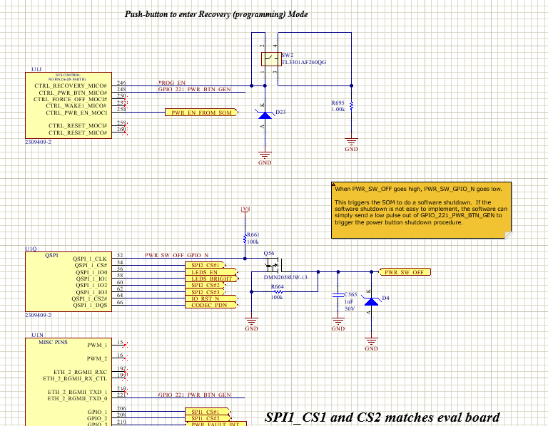
In terms of the power button, we have it connected to a GPIO on the SOM. We don’t have a power button, we have a power switch. When the power switch is turned off, the power switch sends PWR_SW_OFF_GPIO_N low immediately. The idea being that then the SOM can complete a smooth shutdown before the rest of the power control circuit turns off the 5V supply, after about a 5s delay. One way to perform that shutdown would be to send a low pulse to the PWR_BTN signal.
Since PWR_BTN is pulled up internally, I would not expect the shutdown we are seeing to occur.
From my software team, it appears that the GPIO may not be going high?
Any thoughts or advice would be appreciated if you see something glaringly obvious. We are working through it today. I will update you if we figure anything out.
I might make mistakes. Our support team will step in if needed. If I answered your question, please tick the “Solution” checkbox. For follow-up questions to me, please use @ToradexAI in your post.
Did you like my answer?
Hello Ben,
Thank you for your detailed description and the diagram; it helps clarify your setup.
Based on your description and referencing the behavior of the CTRL_PWR_EN_MOCI signal, here are some focused recommendations for troubleshooting:
Key Points to Check
1. CTRL_PWR_EN_MOCI Goes Low After 6 Seconds
Normally, CTRL_PWR_EN_MOCI should remain HIGH to keep the carrier board’s peripherals powered during operation.
If it goes LOW after about 6 seconds, this typically suggests the SoM believes it should be shutting down. This can be triggered by:
A power management signal (such as the power button) being asserted.
The system encountering a critical error early during the boot process (e.g., watchdog, PMIC, or boot failure).
Some unintended GPIO logic causing the system to enter shutdown sequence.
2. Power Button (CTRL_PWR_BTN_MICO#) Behavior
The pin typically expects a momentary LOW for a button press. A long (>5s) LOW pulse causes a forced shutdown, independent of Linux.
The signal is pulled up with a 100k resistor internally to 1.8V RTC rail, so it should stay HIGH if floating or externally pulled high.
If your switch setup is keeping the line LOW at boot, the SoM will begin the shutdown process (reference).
3. GPIO Connected to PWR_BTN
Double-check your circuit: if the signal from your GPIO never goes HIGH or is LOW at boot, the board may see this as an immediate long press.
Troubleshooting Suggestions
Check the Power Button Line (CTRL_PWR_BTN_MICO#)
With an oscilloscope or logic analyzer, monitor the state during and after power up. It should stay HIGH unless intentionally pulled LOW.
If you don’t use a button, consider tying the signal HIGH or leaving it unconnected (the internal pull-up should keep it HIGH).
Check Your Custom GPIO Switch Logic
Ensure that your “power switch” logic does not assert (pull LOW) the CTRL_PWR_BTN_MICO# pin unless you wish to initiate shutdown.
If your GPIO isn’t initialized high, ensure it isn’t floating or accidentally kept LOW.
Review Boot Log for Early Errors
Examine the UART debug output thoroughly for messages indicating early failures.
Look for log lines relating to PMIC, power fault, or kernel panic.
Monitor CTRL_FORCE_OFF_MOCI# During Sequence
This pin, if asserted, can also force the SoM to shut down peripherals and the carrier board (reference).
Summary
A likely root cause: The CTRL_PWR_BTN_MICO# line may be held LOW at startup or not de-asserted by software/hardware, causing a forced shutdown.
Action items: Check that the line is HIGH during normal operation, check the GPIO logic, and verify no other early power-fault conditions exist.
For a deeper dive, you can check the detailed Verdin iMX8M Plus Mezzanine signals documentation and related articles:
If pin 221 is set to low, the system will power off after 5 seconds, as you’re observing. Can you check the state of that pin using an oscilloscope?
It might, if your software team did something incorrectly.
The X1 pin 221, which you selected to control CTRL_PWR_BTN_MICO#, is by default used in U-Boot and Linux as ETH_2_RGMII_TXD0 to interface with the external PHY. Therefore, you cannot control it using a U-Boot command without modifying the U-Boot source code.
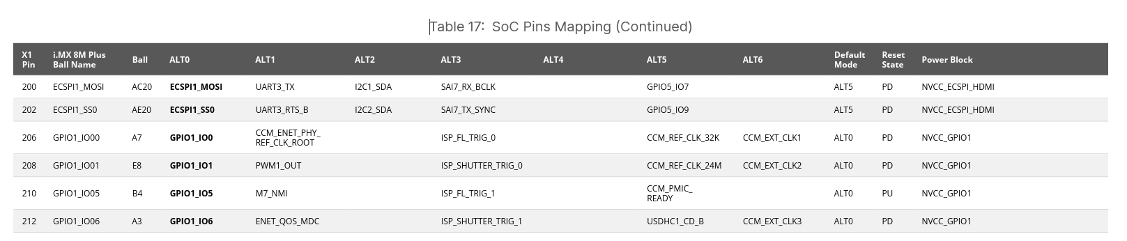
I recommend using pins 206, 208, 210, or 212 instead, as they are designated as GPIOs according to the Verdin specification. No modifications to U-Boot or Linux code are required when using these pins .
Pin 210 is the most preferable option, as it is pulled up after reset and does not require any U-Boot command to prevent the module from force-off.
During testing, we set the GPIO to an output and attempt to drive it to 1. This worked okay on the Verdin board, we were able to set outputs to 1 and 0 using U-boot commands. On the ICVR, if I am probing in the right location (which I double-checked from your diagram), it is not able to drive the output high using the same commands.
I will send them your response regarding ETH_2_RGMII_TXD0 in parallel.
Well then, you should push your developers to modify U-Boot so that pin 221 is set to high or floating immediately after the module starts. The Linux Device Tree should also be updated accordingly.
Sorry for the late reply. Ultimately the software team figured out how to address the issue but I am afraid I don’t have the answer in terms of what specifically was required. I also don’t know if we have completed the solution for doing a clean shutdown, but I believe that was the easier part to implement.