Hi @pkg_su,
Sure! Here I used the example inside the folder below.
SDK_2_9_0_MIMX8UX5xxxFZ/boards/mekmimx8qx/multicore_examples/rpmsg_lite_str_echo_rtos
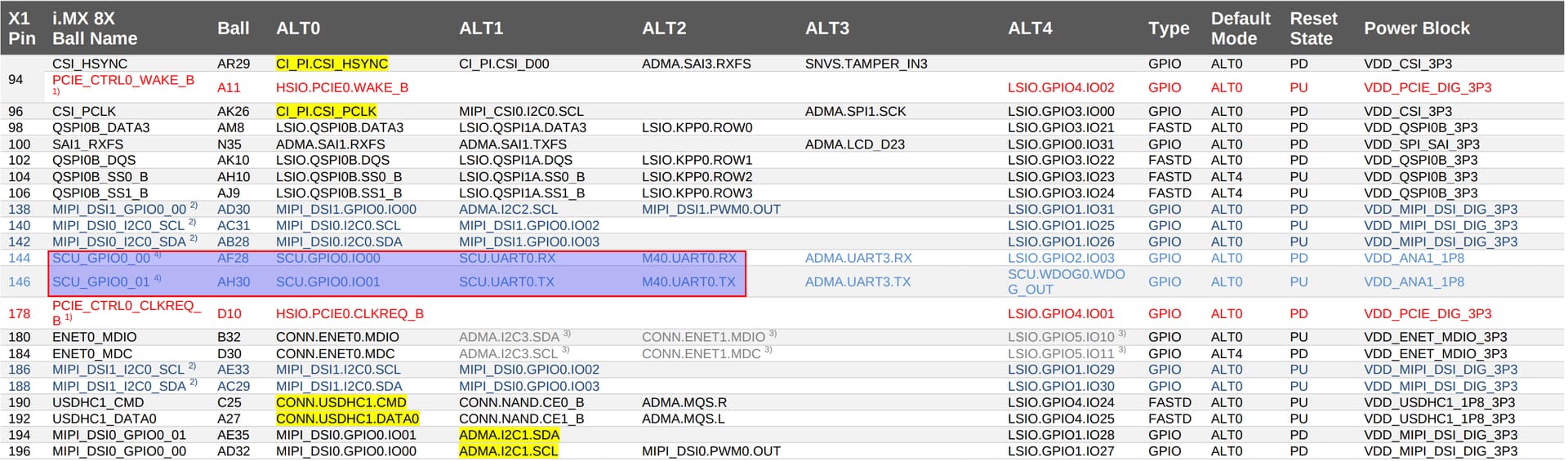
To see the output from Colibri iMX8X M4 UART we need to change the code a little bit. In Colibri, we don’t have access to the default pins that NXP sets inside the pin_mux.h and pin_mux.c. But if we look at the datasheet of Colibri iMX8X, we can see the table below.
We do have access to M4 UART using pins 144 and 146, ALT FUNCTION 2. Then, I changed the code inside the M4 to use these pins:
diff --git a/boards/mekmimx8qx/multicore_examples/rpmsg_lite_str_echo_rtos/pin_mux.h b/boards/mekmimx8qx/multicore_examples/rpmsg_lite_str_echo_rtos/pin_mux.h
index 900d8ef..dbda7f9 100644
--- a/boards/mekmimx8qx/multicore_examples/rpmsg_lite_str_echo_rtos/pin_mux.h
+++ b/boards/mekmimx8qx/multicore_examples/rpmsg_lite_str_echo_rtos/pin_mux.h
@@ -14,10 +14,10 @@
  **********************************************************************************************************************/

 /* ADC_IN2 (coord V32), M40_UART0_RX */
-#define BOARD_INITPINS_M40_UART0_RX_PIN_FUNCTION_ID                 SC_P_ADC_IN2   /*!< Pin function id */
+#define BOARD_INITPINS_M40_UART0_RX_PIN_FUNCTION_ID                 SC_P_SCU_GPIO0_00   /*!< Pin function id */

 /* ADC_IN3 (coord V30), M40_UART0_TX */
-#define BOARD_INITPINS_M40_UART0_TX_PIN_FUNCTION_ID                 SC_P_ADC_IN3   /*!< Pin function id */
+#define BOARD_INITPINS_M40_UART0_TX_PIN_FUNCTION_ID                 SC_P_SCU_GPIO0_01   /*!< Pin function id */

 /* ADC_IN0 (coord U35), M4_I2C0_1V8_SCL */
 #define BOARD_INITPINS_M4_I2C0_1V8_SCL_PIN_FUNCTION_ID              SC_P_ADC_IN0   /*!< Pin function id */
diff --git a/boards/mekmimx8qx/multicore_examples/rpmsg_lite_str_echo_rtos/pin_mux.c b/boards/mekmimx8qx/multicore_examples/rpmsg_lite_str_echo_rtos/pin_mux.c
index 7339c00..391d914 100644
--- a/boards/mekmimx8qx/multicore_examples/rpmsg_lite_str_echo_rtos/pin_mux.c
+++ b/boards/mekmimx8qx/multicore_examples/rpmsg_lite_str_echo_rtos/pin_mux.c
@@ -70,12 +70,12 @@ void BOARD_InitPins(sc_ipc_t ipc)                          /*!< Function assigne
   {
       assert(false);
   }
-  err = sc_pad_set_all(ipc, BOARD_INITPINS_M40_UART0_RX_PIN_FUNCTION_ID, 1U, SC_PAD_CONFIG_NORMAL, SC_PAD_ISO_OFF, 0x0 ,SC_PAD_WAKEUP_OFF);/* IOMUXD_ADC_IN2 register modification value */
+  err = sc_pad_set_all(ipc, BOARD_INITPINS_M40_UART0_RX_PIN_FUNCTION_ID, 2U, SC_PAD_CONFIG_NORMAL, SC_PAD_ISO_OFF, 0x0 ,SC_PAD_WAKEUP_OFF);/* IOMUXD_ADC_IN2 register modification value */
   if (SC_ERR_NONE != err)
   {
       assert(false);
   }
-  err = sc_pad_set_all(ipc, BOARD_INITPINS_M40_UART0_TX_PIN_FUNCTION_ID, 1U, SC_PAD_CONFIG_NORMAL, SC_PAD_ISO_OFF, 0x0 ,SC_PAD_WAKEUP_OFF);/* IOMUXD_ADC_IN3 register modification value */
+  err = sc_pad_set_all(ipc, BOARD_INITPINS_M40_UART0_TX_PIN_FUNCTION_ID, 2U, SC_PAD_CONFIG_NORMAL, SC_PAD_ISO_OFF, 0x0 ,SC_PAD_WAKEUP_OFF);/* IOMUXD_ADC_IN3 register modification value */
   if (SC_ERR_NONE != err)
   {
       assert(false);
Then, to see the UART inside the M4, we need to disable it from the Linux Kernel. Otherwise, Linux will enable this UART during the boot process and we won’t be able to see the messages on your Screen.
So I booted up my Linux (here I’m using the Reference Minimal Image), and enable the overlay called colibri-imx8x_disable-cm40-uart_overlay.dtbo:
root@colibri-imx8x-06995803:~# cat /boot/overlays.txt
fdt_overlays=colibri-imx8x_parallel-rgb_overlay.dtbo colibri-imx8x_ad7879_overlay.dtbo display-vga_overlay.dtbo colibri-imx8x_disable-cm40-uart_overlay.dtbo
Then I rebooted my module and stopped at the uBoot terminal.
Next, I compiled my code and loaded it inside the Cortex-M4. Here I’m using a Colibri Evaluation Board and a USB to TTL converter to see the output of M4 on my computer (hooked up on pins SODIMM_144 and SODIMM_146). For more information on how to do that, please follow these guides: High performance, low power Embedded Computing Systems | Toradex Developer Center.
As soon as you run the M4 Code, you should see this message on your screen:
RPMSG String Echo FreeRTOS RTOS API Demo...
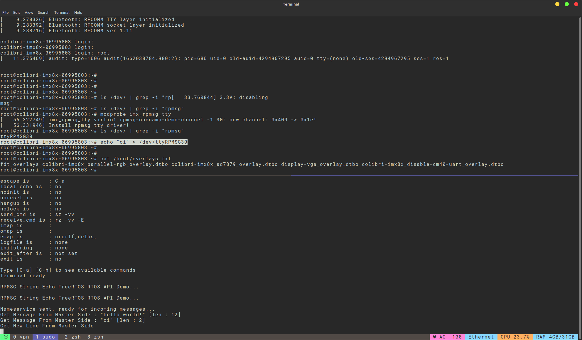
Now boot the Linux Kernel (running boot command on uBoot) and load the kernel module for the RPMSG:
root@colibri-imx8x-06995803:~# modprobe imx_rpmsg_tty
[   56.322749] imx_rpmsg_tty virtio1.rpmsg-openamp-demo-channel.-1.30: new channel: 0x400 -> 0x1e!
[   56.331946] Install rpmsg tty driver!
root@colibri-imx8x-06995803:~# ls /dev/ | grep -i "rpmsg"
ttyRPMSG30
Now you can simply send messages between Cortex-A and Cortex-M4:
root@colibri-imx8x-06995803:~# echo "oi" > /dev/ttyRPMSG30
Please, let me know if all steps are clear and if you need any extra help with that.
Best regards,
Hiago.