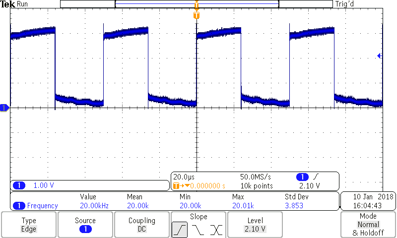
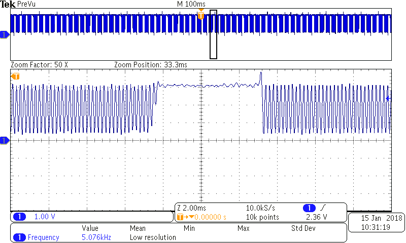
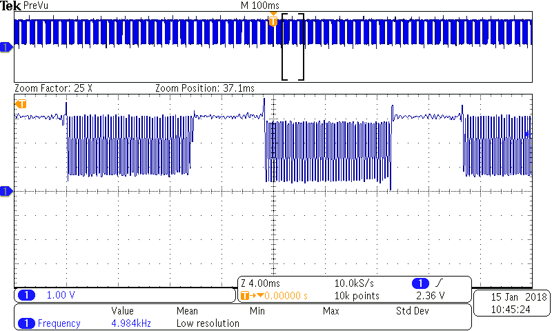
We found a ~790ms power pulse in our system. Looking at the backlight control a scope could easily sync on the 10KHz pwm. However, when you scale the horizontal down to low hz, there is another on/off cycle on this pwm signal. Guessing the FSM prescaler is switching the PWM channel on and off. Attached several pictures on this showing high/low sweep rates with low and medium duty cycles for brightness. Is there a solution to make the backlight control on all the time with 10KHz pwm?
Yes, it won’t have any aliasing errors if you sample according to sample theorem. A sufficient sample-rate is therefore 2B samples/second. A 100 MHz input does not say that your device is sampling at 100MHz. In fact, according to the last screenshot the device states that it is sampling with 10.0kS/s… Sample according to sample theorem and you should not see any of the aliasing errors…
Hi pgrosshart
Could you describe which hardware and software version of the toradex module are u using? Additionally which carrier board?
best regards
Jaski
We are using the VF50 IT, V1.2A module. The carrier is our custom board.
Best regards,
Paul
Hi Paul
I checked your pictures. You are measuring a signal with a frequency of 20kHz. At higher sweep rates, your measurements are correct. But at lower sweep rates, you are not respecting the Nyquist/Shannon theorem. You should select peak-detetction mode instead of normal mode for measurement. Once, this is done, we can talk about your problem of 790ms power pulse.
Best regards, Jaski
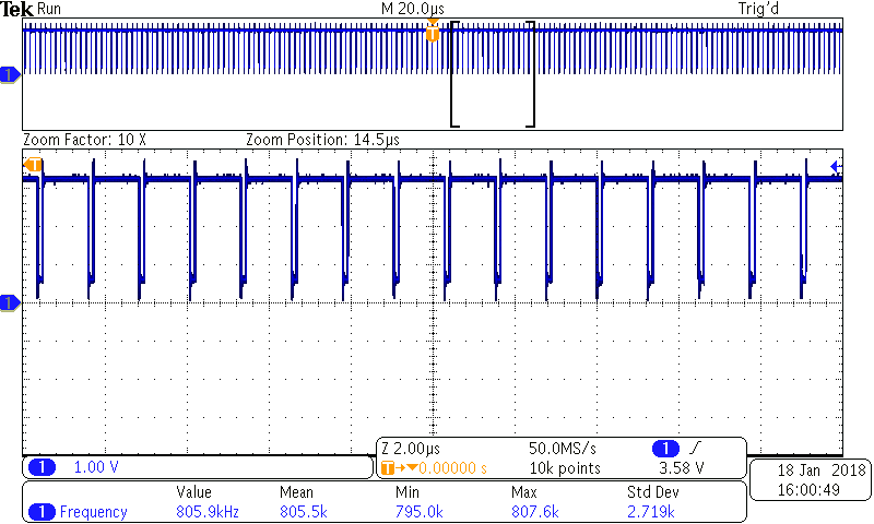
Right on 20KHz vs. 10KHz - I had adjusted the devicetree from the default. The purpose of under sampling on purpose was to show the slow on and off. We “cured” the 790ms power pulse by changing the PWM to a very high number - above 200KHz. This raised the low frequency on/off to above a couple of KHz, allowing filtering of the power pulses.
Hi Paul,
if there is a slow on and off, then you will see this all the time. Under Sampling does not help you find anything. You should record the signal over sometime to find the slow on and off.
best regards, Jaski
Hi Paul
You are still not respecting the Nyquist/Shannon Theorem, thats why you see strange things. Could you measure for a signal of 10kHz with at least 100k Points with at least 100kS/s during 10ms.
what is the exact model of your oscilloscope?
Best regards, Jaski
I think I have a good understanding of Nyquist… the problem is the higher switching frequency is so far above the low frequency that measuring a 10KHz signal will miss showing the low frequency component. Looks about 10,000:1 ratio. My original pictures were to show different views of the same signal from the backlight without changing anything other than the horizontal scale. Triggering would occur on any of the 10KHz switching transitions so its a 1 in 10,000 chance to catch an edge of the low frequency switching. The amplitude is not any different so triggering won’t be easy on the leading / falling edge. I could try and trigger on the spike at the start/stop of the higher frequency periods, but I doubt I will see anything better.
This scope is a Tek MDO3014. A 100 MHz input should not have any aliasing errors.
Here are two screen shots. No change in what is measured. Only the horizontal. One at 100KS/s, and one at 50MS/s.
Hi Paul
Thanks for the measurement pictures. On your two measurements, the frequency is different. Was there a change of frequency for the measurements? Is there still a problem with your pwm signal?
Hello,
Apologies for not a complete story. We raised the PWM frequency to ~800KHz to get the low switching characteristic above a few KHz - which we can filter with a small re-work. The reason we got concerned is the analog parts of our design had this switching ‘bleed’ through to analog outputs. This freq change has reduced but not eliminated low mV level noise, if the low frequency switching were eliminated we would change to PWM back to 10KHz.
On the pictures, the signal being measured is not altered at all for each posting. They are changed from posting to posting. First was a freq. of 20KHz, last was at 800KHz (which gave us relief from LF noise). I have the unit that was used for measurements set aside and can do whatever test you would like to see.
We are testing today on another batch of units with this change - I think this has also eliminated a intermittent flicker we saw on several system’s LCDs while conducting thermal testing. My impression of a few that have been changed is the screen looks better but that’s an impression without data.
Hello Paul,
Thanks for the information. Let us know, if there is still an issue.
Please, how did you manage to raise the PWM frequency to ~800 KHz?
@pgrosshart: Please, how did you manage to raise the PWM frequency to ~800 KHz?