Problems with virtual memory mapping for flextimer1 in colibri imx7 and what other peripherials are required for implementing pwm along with quadrature encoder mode?

Hi I am trying to use flex timer 1 in quadrature mode. I tried to do virtual memory mapping with a structure in order to initialize registers required for flextimer. The program looses connection with the device as soon as memory mapping is done. I am currently deploying the code using ethernet port and providing power supply using the mini usb port. Can somebody also tell me the other dependencies I need to address while using the flextimer to generated pwm?

My code is given below:

#include "stdafx.h"
#include "mapmem.h"
#include "clk_imx7.h"
#include "gpio_imx7.h"
#include <windows.h>

#define CCM_BASE_ADDR 0x30380000
#define CCM_CCGR128 0x30384800
#define CCM_TARGET_ROOT110 0x3038B700

typedef struct{
    UINT32 FTM_SC;
    UINT32 FTM_CNT;
    UINT32 FTM_MOD;
    UINT32 FTM_C0SC;
    UINT32 FTM_C0V;
    UINT32 FTM_C1SC;
    UINT32 FTM_C1V;
    UINT32 FTM_C2SC;
    UINT32 FTM_C2V;
    UINT32 FTM_C3SC;
    UINT32 FTM_C3V;
    UINT32 FTM_C4SC;
    UINT32 FTM_C4V;
    UINT32 FTM_C5SC;
    UINT32 FTM_C5V;
    UINT32 FTM_C6SC;
    UINT32 FTM_C6V;
    UINT32 FTM_C7SC;
    UINT32 FTM_C7V;
    UINT32 FTM_CNTIN;
    UINT32 FTM_STATUS;
    UINT32 FTM_MODE;
    UINT32 FTM_SYNC;
    UINT32 FTM_OUTINIT;
    UINT32 FTM_OUTMASK;
    UINT32 FTM_COMBINE;
    UINT32 FTM_DEADTIME;
    UINT32 FTM_EXTTRIG;
    UINT32 FTM_POL;
    UINT32 FTM_FMS;
    UINT32 FTM_FILTER;
    UINT32 FTM_QDCTRL;
    UINT32 FTM_CONF;
    UINT32 FTM_SYNCONF;
    UINT32 FTM_INVCTRL;
    UINT32 FTM_SWOCTRL;
    UINT32 FTM_PWMLOAD;
}tFTM_REGS,*ptFTM_REGS;


BOOL FTM_ConfigureIos(HANDLE hGpio)
{
    int i;
    BOOL fSuccess = TRUE;
 
    const uIo eimIo[] =
    {
        COLIBRI_PIN( 30),   // flextimer1.PHA
        COLIBRI_PIN( 67),   // flextimer1.PHB
        COLIBRI_PIN( 29)     //flextimer1.CH[7]
        
    };
 
    /// The Flextimer functionality is on ALT 5 and the channel is on ALT 2.
    for (i = 0; i < 2; i++) //_countof(eimIo)
        fSuccess &= Imx7Gpio_SetConfigString(hGpio, eimIo[i], NULL, L"AltFn=5,dir=in", StoreVolatile);
    
    fSuccess &= Imx7Gpio_SetConfigString(hGpio, eimIo[2], NULL, L"AltFn=2,dir=out", StoreVolatile);
    return fSuccess;
}
 

int wmain(int argc, _TCHAR* argv[])
{
    BOOL   fSuccess = TRUE;
    HANDLE hMap;
    HANDLE hGpio;

     ptFTM_REGS pFtm1Reg;

    ptFTM_REGS pFtm1Reg;

    UINT32 *tmp_ptr=NULL;
    //volatile DWORD *clkRegs;
    //volatile DWORD tmp;
    //volatile DWORD *targetAddr;
    char usr_input;
    
    hMap=Map_Init();

    hGpio = Imx7Gpio_Init(NULL);
    fSuccess = FTM_ConfigureIos(hGpio);
    fSuccess &= Imx7Gpio_Deinit(hGpio);
    printf("%d\n",fSuccess);
    
    pFtm1Reg=(ptFTM_REGS)Map_MapMemory(0x30640000,0x1000); //FTM1_SC is at 0x30640000

   //  FAILS AT THIS POINT  *********************************************
 
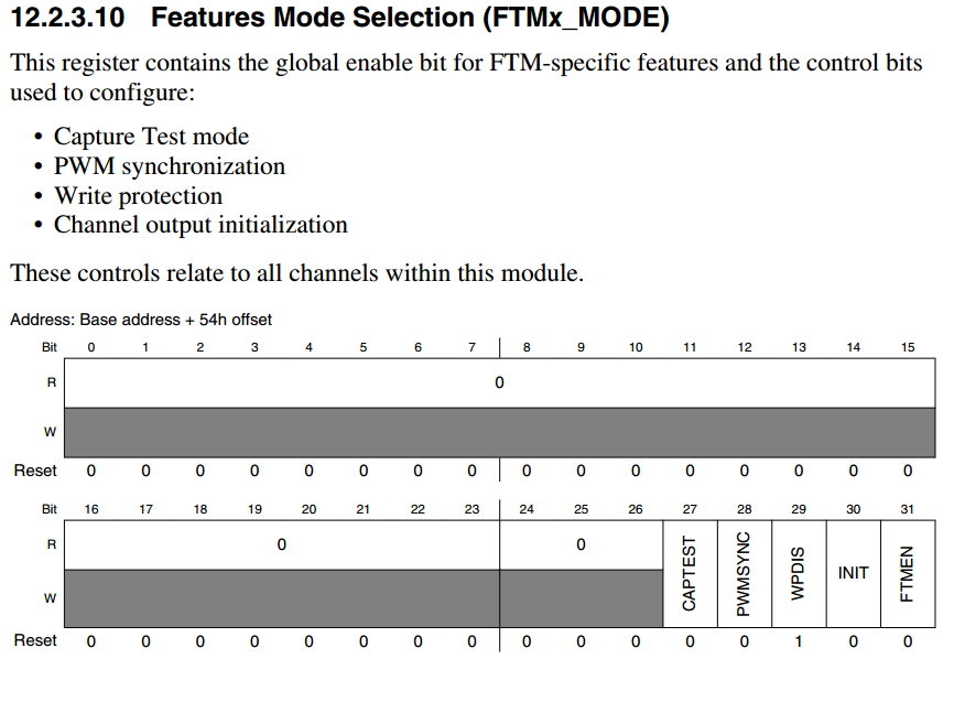
    //initialization is mentioned on pg 4197

    pFtm1Reg->FTM_MODE=0xE0000000;

    pFtm1Reg->FTM_POL=0x00000000;   //24 0 channel polarity is active high

    pFtm1Reg->FTM_OUTMASK=0x00000000;   //24 0 works normally 

    pFtm1Reg->FTM_MOD=0xFFFFFFFF;   //16-32 ffff modulo value used in case of overflow

    pFtm1Reg->FTM_CNTIN=0x00000000; //intial counter value

    pFtm1Reg->FTM_SC=0x90000000;    // 27-28 01 system clk
                                    // 29-31 001 divide by 2
    
    pFtm1Reg->FTM_C7SC=0x18000000;  //channel status and control register
                                    //26-27 01 mode selection output compare
                                    //28-29 10 edge selection clear on match 

    pFtm1Reg->FTM_C7V=0x00100000; 

    pFtm1Reg->FTM_FMS=0x00000000;   //25 0 write protection disabled    
    
    pFtm1Reg->FTM_SYNC=0x00000000;  //used for PWM sychronization 

    pFtm1Reg->FTM_OUTINIT=0x00000000;   //output initialization value for channels 

    pFtm1Reg->FTM_SYNCONF=0x00000000;   //PWM synchronization configuration, SWOCTRL, INVCTRL
                                        //and CNTIN registers synchronization

    pFtm1Reg->FTM_COMBINE=0x00000000;   //configure the synchronization, deadtime
                                        //insertion, Dual Edge Capture mode, Complementary,
                                        //and Combine mode for each pair of channels (n) and (n+1)     
    
    pFtm1Reg->FTM_CONF=0x00000000;  //global time base for other FTM //unsure of use 

    pFtm1Reg->FTM_CNT=0x00000000;   // initialize count 
    
    
    pFtm1Reg->FTM_QDCTRL=0xF0000000;    //24 0 phase A input filter enable 
                                        //25 0 phase B filter input enable 
                                        //26 0 phase A input polarity 
                                        //27 0 phase B input polarity 
                                        //28 1 qadrature decoder mode 
                                        //29 1 FTM counter direction 
                                        //30 1 timer overflow direction 
                                        //31 1 quadrature decoder mode enable  

    pFtm1Reg->FTM_PWMLOAD=0x01800000; //22 1 load enable MOD, CNTIN, and CV
                                      //24 1 channel 7 selected for compare match 
    while(TRUE){
        scanf("%c",usr_input);
        if(usr_input){
            printf("\n encoder count: %zu",pFtm1Reg->FTM_CNT);
        }
        else if(usr_input=='Q' || usr_input=='q')
        {
            break;
        }
    }
  
	return 0;
}

Hi,
I was able to figure out a part of the problem. You need to intialize the flextimer clock using the CCM_CCGR128 clock gating register and CCM_TARGET_ROOT110 register in target interface before you can do the mapping. But when I try to write to the virtual address I am not able to see any change in the register values. Does anybody have and idea why this could be happening?

Dear @tank
You probably need to read and write these registers in Kernel mode.
You can easily do this by using the functions Map_MemoryRead() and Map_MemoryWrite() functions, which are part of our Toradex CE Libraries.

Regards, Andy

Dear @tank,

tFTM_REGS should be volatile. Use any one typedef volatile struct{ or volatile ptFTM_REGS pFtm1Reg;

How did you map the address for CCM_CCGR128 and CCM_TARGET_ROOT110? Could you please share code snippet.

If you want to try set/clear a particular bit register, you can use Reg access Tool

Andy,

I am able to write to the mapped resgisters if I compile and deploy the solution in RELEASE mode. Whereas I am unable to write to the mapped registers if the code is running in DEBUG mode. This is irrespective of using the above mentioned fuctions or writting to the virtual registers directly. I just wanted to gain more understanding why this could occur?

Dear @tank,

The processor peripheral register must be declared with volatile. Use typedef volatile struct{ or volatile ptFTM_REGS pFtm1Reg. Please read this document for more information about volatile.

Please use Reg access tool to manually verify individual processor peripherals registers access.

Let me know if it doesn’t help.

@raja.tx ,

I had to add this section before I could write to flextimer registers.

#define CCM_BASE_ADDRESS 0x30380000
#define CCM_CCGR128 0x30384800
#define CCM_TARGET_ROOT110 0x3038B700

volatile DWORD *clkRegs;
volatile DWORD *targetAddr;

clkRegs  = (DWORD *)Map_MapMemory(CCM_BASE_ADDRESS, 0x10000);
targetAddr =  clkRegs + (CCM_CCGR128 - CCM_BASE_ADDRESS)/4;
*targetAddr &= ~0xFFFFFFFF;
targetAddr = clkRegs + (CCM_TARGET_ROOT110 - CCM_BASE_ADDRESS)/4;
*targetAddr |= 0x10000000;
targetAddr = clkRegs + (CCM_CCGR128 - CCM_BASE_ADDRESS)/4;
*targetAddr |= 0x03;

Hi Andy,

We need some more inputs to understand the access to processor peripheral registers. How do we ascertain whether the to access a peripheral register(register-set) needs to be accessed using Map_MapMemory() or Map_MemoryRead().

Thanks
Deepak

Dear @tank,

Thank you for posting your findings. Did you find the solution? Do you need any support from our side?

Dear @raja.tx, I am trying to initialize the quadrature decoder mode with ouput compare match. The code given below the intialization of registers as per the instructions given in the manual. I do see change in the FTM count register even though the enoder is not moving. Are there any other changes I need to make to the FTM registers or any other registers in conjuntion to make the code functional

FTM_FMS=0x00000000; //6 WPEN 0 Write Protection Enable
FTM_MODE |=(1<<FTMEN); 
FTM_SC &= ~((1<<CLKS_0)|(1<<CLKS_1)); 
FTM_CONF |=(1<<BDMMODE_1)|(1<<BDMMODE_0);
FTM_POL=0x00000003
FTM_OUTMASK =0x0000007A; 
FTM_QDCTRL &= ~((1<<QUADMODE)|(1<<QUADEN));
FTM_CNTIN=0x00000000;
FTM_C7SC=0x0000001C; 
FTM_COMBINE=0x00000000;
FTM_C7V=0x00006000; 
FTM_DEADTIME=0x00000000; 
FTM_FILTER=0x00000044; 
// FTM_INVCTRL=0x00000000; //not used
//FTM_SWOCTRL=0x00000000; //not used
// FTM_OUTINIT=0x00000000; //not used
FTM_SC |=(1<<CLKS_0); 
FTM_QDCTRL |=(1<<PHBFLTREN)|(1<<PHAFLTREN)|(1<<QUADEN);
FTM_MODE &=~(1<<FTMEN);
FTM_SYNCONF |= (1<<SYNCMODE)|(1<<SWRSTCNT)|(1<<SWWRBUF)|(1<<SWOM); 
FTM_SYNC |= (1<<SWSYNC) |(1<<CNTMAX)|(1<<SYNCHOM) ; 
FTM_CNT=0x00000000; //0-15 COUNT 0x000 Counter Value

Dear @tank,

Just for confirmation, Did you verify GPIO alternate functionality, Is that correct setting?
Internally, we never experiment with this feature. We need a little more time to look in the TRM and get back you if we find anything.

Best regards and Good Luck!

Dear @raja.tx,
I have initialized the gpio for phase A and phase B. The pins 30 and 67 on Colibri SOM are initialized as AltFn=5,dir=in, pull=none .

Dear @tank,

Thank you for the reply. Could you please share sample application code to look the topic on our side.

Dear @tank,

Could you please check here : https://os.mbed.com/search/?q=quadrature+FTM, you might get some clue for your query.

Are you looking quadrature decoder right? I guess, quadrature encoder mistakenly is written here?

Dear @raja.tx,

Attached the code

link text

Dear @raja.tx ,

Yes, I am looking for quadrature decoder mode.

Dear @tank,

I would need a few more days to work on this and get back you. Could you please wait for a few days?

Dear @tank,

Did you notice? FTMEN is bit 31 and WPDIS is bit 29 in the FTM_Mode register, it is not 0 and 2 bit respectively. This is strange.

Could you please check all the register bits? Let us know is that cause for the issue.

Dear @raja.tx ,

Kindly check this link, NXP has made a mistake and has not rectified it in the reference manual yet.

Dear @tank,

Thank you for the reply. Your source code seems to be fine. We never experience this feature from Soc also we don’t have rotary encoder hardware here to properly verify. At the moment, we can confirm the WinCE BSP doesn’t block or use anything related to this feature.
Could you please help yourself to find the solution to this problem?
Please try to get help from NXP community : https://community.nxp.com/, there you might get some references or clues to solve the issue.

Please feel free to contact us if you face any other issues with our toradex HW and SW.

Thank you for your understanding.