I’m trying to get the multi-touch solution running on our Colibri board, with the Toradex 7" capacitive display connected and working.
I downloaded the HW adapter for the Atmel mXT1066t2 from this page. After getting the include and library paths for the Toradex CE libraries straightened out it builds just fine. It also runs fine, and the I2C stuff appears to be working.
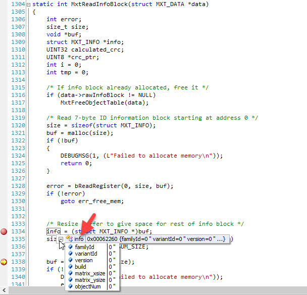
However, when I run it I get errors in MtxReadInfoBlock, specifically because the info block seems to contain nothing:
My suspicion is that there is something else that needs to be done, as specified in the display data sheet:
The Cap touch controller must be programmed with firmware for Toradex, file “ LTCTP070-3-GG_mXT1066T2_tdx_20170911. xcfg”
The only reference I could find to that file was in this question from Pedro. The solution contains an archive to download (which contains the.xcfg file and what appears to be an executable called mtx-app) along with instructions on how to load the file. The instructions are for the Linux OS and I could not find any reference to the equivalent thing for WinCE. The .xcfg file does contain records for family, variant, version, etc so I’m pretty sure this is the missing thing.
Is there any information about this subject for the WinCE OS?
Thank you for contacting support and with detailed information about the issue.
The touch controller configuration program can only be done in Linux and it is not available for WinCE.
IMX6 can be programmed with Linux over TEZI, it is quite easy then program the configuration parameter and it will be persistent. Again, you can program WinCE and continue your development.
Please feel free to contact us if you need any help on this.
Still a bit of a problem. I loaded Linux on my board and executed the described procedure. I don’t have I2C 3 (only 0, 1, and 2 show up in /dev) so I tried them all. None worked.
Here is what I see with I2C 1 and 2. With I2C 0 the error is “No such device or address (6)”
sh-4.3# ./mxt-app -d i2c-dev:1-004a --load LTCTP070-3-GG_mXT1066T2_tdx_20170911.xcfg
Version:1.27-7-g6d84bb0 Registered
i2c-dev adapter:1 address:0x4a Error
Input/output error (5) writing to i2c
Failed to read ID information
This means either I have a HW problem or there is some other configuration that needs to be done first. I have an analyser that can examine the I2C traffic, but is there anything else I should try before that?
If you connected display’s I2C lines to Iris X16 pins 5.6.7 it will correspond to Linux i2C 2.
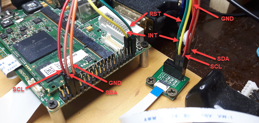
Could you specify version of your display? Or provide a picture please.
OK, so I connected my analyzer to pins 5 (SDA) and 6 (SCL) on the Iris connector X16.
In Linux, I ran the following command with 0, 1, and 2 substituted for BUS#:
i2cdetect -a -y -r BUS# 0x4a 0x4a
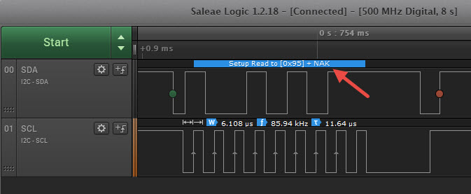
The result was the usual double-dash indicating no device. My analyzer captured the following. Note the NAK. The capture was identical for all I2C busses.
The Reset pin(106) is set to output and 1 and getting following response for the i2cdetect command. “Colibri-iMX6_LXDE-Image 2.8b1.64 20171229” release is programmed on the Colibri - iMX6 module.
root@colibri-imx6:~# i2cdetect -a -y -r 2 0x4a 0x4a
     0  1  2  3  4  5  6  7  8  9  a  b  c  d  e  f
00:
10:
20:
30:
40:                               4a
50:
60:
70:
Was that touch controller working partially with WinCE? If it is not at all working with WinCE and Linux then probably touch controller gone bad and you need to initiate RMA. May I know from which country shop you bought this display?
Well, the 2nd display arrived and it fails exactly like the 1st one. The I2C trace looks perfectly normal except for the NAK. Actually the I2C clock looks a bit slow at 86 KHz, but that should not prevent it from working. It simply looks like there is no device at I2C address 0x4A. I checked and re-checked the wiring, and I also loaded the latest Linux image (I think it was 2.8B3). Still no success. I reloaded WEC7 and wrote a small test program to try to read from I2C address 0x4a, subaddress 0x95 (like i2cdetect does) and it fails there as well. I can only conclude that somehow we have two defective displays, as unlikely as this is. We have a guy here that will deal with the returns/exchanges.
Please mention this community post in the RMA comments field, otherwise we will probably ask you again to do the same tests. I apologize for the inconvenience.
The good news is that everything works. The bad news is that it was an error on my part.
When connecting the adapter between the X16 header on the Iris board and the display, I had inserted the 10-pin ribbon cable upside down
On every other ribbon connection, the contact side of the cable was facing the PCB (i.e. blue side up). Between the adapter and the display, I finally discovered that the reverse is true.
With the cable inserted incorrectly, I had actually buzzed out the connection between the X16 header and the 10-pin ribbon connector on the display, and was satisfied that everything was OK. It was only much later that I noticed the I2C test pads on the display PCB itself, and that those pads were connected to the other side of the 10-pin ribbon connector.
So I flipped the cable over and sure enough there was connectivity right to the I2C test pads on the display. And suddenly everything works fine. I managed to program the firmware into the two original displays without incident.
So anyway, none of the boards are defective and we will be keeping all of them.
Thanks very much for your excellent support in this matter, as usual, and sorry for wasting your time.