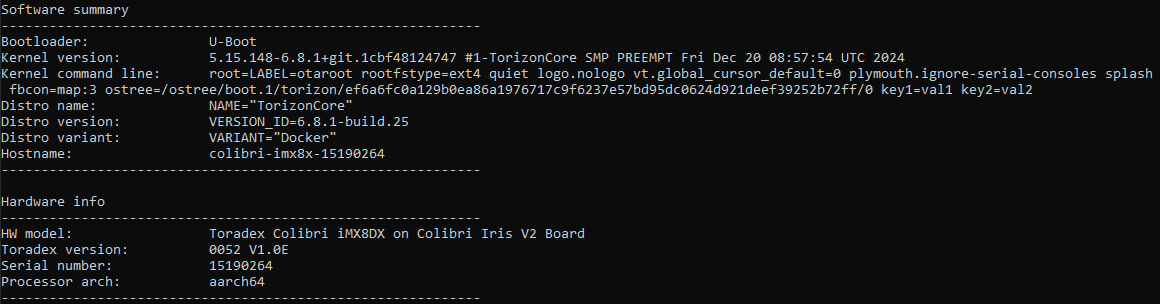
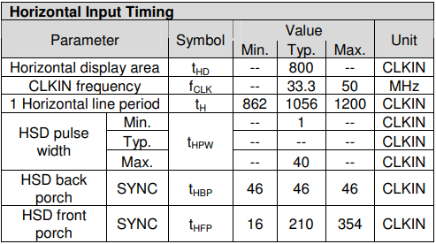
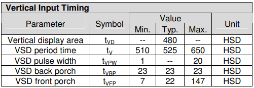
I am working on integrating the parallel RGB interface of a Colibri-IMX8DX module with a custom display adapter that was previously developed for a T30 module. Here is my system summary:
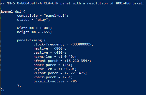
I’ve tried using typical values from the data sheet as well and get the same result. I also read on another post setting pixelclk-active to 0 may fix some issues. I’ve kept it at 1 as wll, like in the provided overlay for the 7-inch screen. I could not find any information on where this value comes from, though.
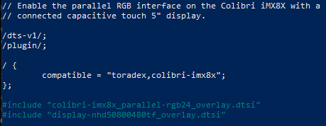
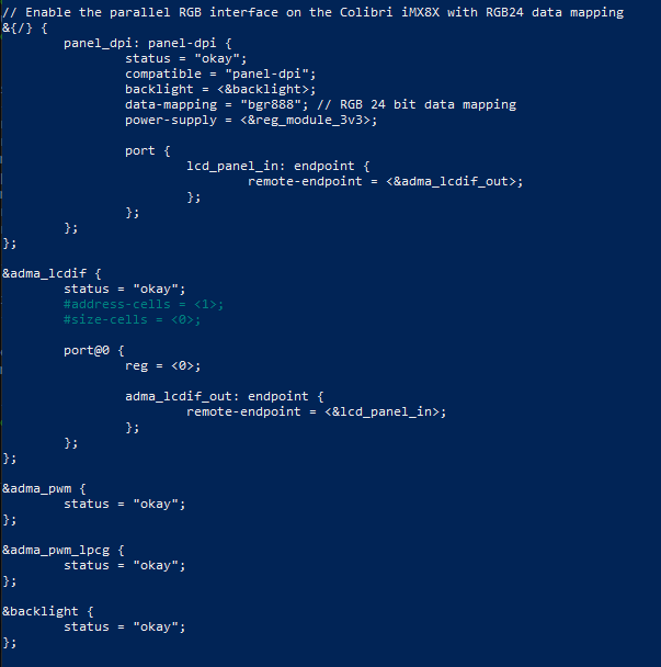
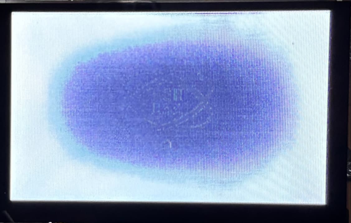
I can compile and push a new image to the module successfully with these overlays however I’m getting some interesting results. If I power cycle the system with my new image, the screen turns white for a few seconds and then goes to black. If I push an application, there is no display output. As shown in the images below, If I reboot the system, I can see the splash screen (kind of) but obviously there is something very off. Still, the output ends up being black
I’m wondering what I have missed, Have I used the correct display timing values? I’m not really sure where to go from here. Any help would be kindly appreciated!
Ensure the base device tree includes all required nodes before applying the overlay.
Confirm that your overlay is compatible with your kernel version.
Verify that the overlay is correctly listed in the /boot/overlays.txt file. (source)
Kernel Consideration:
Recent community feedback suggests that using the downstream kernel instead of linux-toradex-upstream may resolve overlay application issues on the Colibri iMX8X. You can find more details in the community discussion (source).
If you need further assistance on any of these points, feel free to ask!
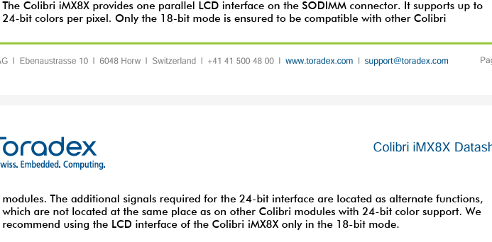
@alex.tx I missed this piece of information, so thank you. I will look into setting up the screen to run in 18-bit mode, if possible, to see if I get correct output.
After looking into it more, the display adapter being used ties the LSB bits of each color to ground so that it effectively operates in 18-bit mode. I re-compiled using 18-bit data-mapping for the RGB parallel interface and get a very similar result. The only difference is that the images seem just a bit clearer. Any other suggestions? Thank you again for your time.
It looks like some kind of hardware issue to me.
Please share the details of your carrier board, the adapter schematic, how it is connected to the carrier board, and the display datasheet
Apologies for the late reply. Getting the screen to work was just a part of the integration effort. I also need to get touch configured as the touch signals are fed through the 40-pin extension connector (x16). I’ve had this connected the whole time while just trying to get the screen to work as I was planning on tackling this next. I didn’t realize the Backlight Enable was also being fed through the x16 connector as well via pin 20. This is more than likely the reason for the behavior I’m seeing. My question now is, where do I configure this? Should it be written in the &backlight node in the colibri-imx8x_parallel-rgb24_overlay.dtsi or somewhere else?
Could you please clarify which X16 connector you are referring to?
Also, please share details about your carrier board, the adapter schematic, and how it is connected to the carrier board.
I am using the Iris carrier board V2.0B. The X16 connector I am referring to is from section 3.9.3, on page 27 of the Iris Carrier Board Datasheet. Can I send you the adapter schematic privately? There are 2 connections between the display adapter and the Iris Carrier Board.
Iris Unified Interface Display Connector (X3) to Display Adapter (X6)
Iris Extension Connector (X16) to Display Adapter (J2)
On the Iris board, X16 pin 20 is connected to SODIMM_45, which is not the default pin for backlight control. In our design, we use SODIMM_71 to enable the backlight and PWM_A (SODIMM_59) to control its brightness.
You can share your schematic privately by sending it to support.us@toradex.com. Please include link to this tread in your e-mail.
I am still waiting on confirmation from my company if I am able to send the adapter schematic. In the meantime, I’ve been able to get the display to work although I think I may have the bit configuration of the backlight enable pin incorrect because the screen still behaves as it did until the splash screen is shown, at which point I have proper output on the screen. This is how I got it to work:
#include "dt-bindings/pinctrl/pads-imx8qxp.h"
// Enable the parallel RGB interface on the Colibri iMX8X.
&{/} {
panel_dpi: panel-dpi {
status = "okay";
compatible = "panel-dpi";
backlight = <&backlight>;
data-mapping = "bgr666";
power-supply = <®_module_3v3>;
port {
lcd_panel_in: endpoint {
remote-endpoint = <&adma_lcdif_out>;
};
};
};
};
&adma_lcdif {
status = "okay";
#address-cells = <1>;
#size-cells = <0>;
port@0 {
reg = <0>;
adma_lcdif_out: endpoint {
remote-endpoint = <&lcd_panel_in>;
};
};
};
&adma_pwm {
status = "okay";
};
&adma_pwm_lpcg {
status = "okay";
};
&backlight {
status = "okay";
};
&colibri_gpio_keys {
status = "disabled";
};
/* Colibri LCD Back-Light GPIO change to SODIMM 45 instead of 71 */
&pinctrl_gpio_bl_on {
gpioblongrp {
fsl,pins = <IMX8QXP_QSPI0A_DATA1_LSIO_GPIO3_IO10 0x60>;
};
};
I am now facing an issue with the touch controller. The capacitive touch pins of our display adapter match those of the atmel touch adapter but uses a Focaltech driver, which the Toradex Linux directory has a driver for. I also know the address is 0x38. My problem is that the driver does not show up when using lsmod after the new image has been pushed. Here is the device tree overlay I am using. I used Focaltech’s example here: FT5X26-Focaltech-Drivers/FT5426_Linux_Driver/docs/focaltech-ts.txt at master · NewhavenDisplay/FT5X26-Focaltech-Drivers · GitHub
Hi Alex, I’ve tracked down what I think is the solution. There is a driver in build 6.8.1-25 named edt-ft5x06, which works for that family of Focaltech IC’s, and is enabled in the kernel. The screen I am working with uses a FT5426 driver, which is not compatible with the edt-ft5x06 driver. I did notice though that there are more drivers available; focaltech_core and focaltech_i2c, but they are not enabled in the kernel. Are there any builds currently with these additional focaltech drivers enabled? If not, are there plans to make them enabled anytime soon?
Thank you again for all of your time and assitance!
We do not provide such builds and currently have no plans to do so. However, you are free to build your own custom kernel and include any drivers you require.
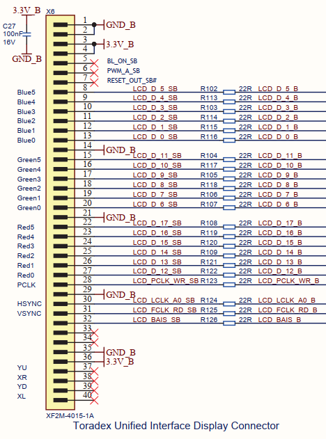
Thank you for getting back to me. I’ve gotten the screen to show output and was able to get the touch driver working. However, the output seems to be missing the MSB bit of just the blue channel. For instance, the RGB color (224, 224, 224) is showing as a shade of yellow instead of gray. If you remove the MSB of blue, you get RGB (224, 224, 112), which is indeed the color I’m seeing on the screen. The display adapter board I am using has the following connector for the unified display connector
I double checked the cable and adapter. I measured continuity all the way through and even tried a different cable. I could not find any issues on the adapter or cable.
All your settings and the fbset output appear to be correct. The only explanation for the color distortion you’re observing that I can suggest at this point is a potential hardware issue.
Do you have another unit of the display available for testing?