I am currently designing a prototype of a carrier board with the OSM-iMX93.
Some points in the datasheet are not enitrely clear to me:
Boot mode selection:
iMX93 SOC bootmode pins are multiplexed with OSM pins:
BOOT_MODE0 - UART_CON_TX
BOOT_MODE1 - UART_C_TX
BOOT_MODE2 - SPI_B_CS0#
BOOT_MODE3 - SPI_B_SCK
The datasheet points out that 10k Pull-Downs are placed on the OSM for UART_C_TX, SPI_B_CS0# and SPI_B_SCK. Also a 10k PU controlled by FORCE_RECOVERY# is placed for UART_CON_TX.
I also found a note in the datasheet, that the boot-pins are somehow isolated from the OSM during POR.
My goal is, that the OSM boots from eMMC unless ForceRecovery is asserted low.
What would be the recommended way to achieve this?
RTC_PWR Pin
Is it correct, that the supply voltage range for RTC_PWR is 1.6V to 5.5V?
Do i need to add a Diode to prevent unintended charging of the backup battery?
Soldering / contact technology
The OSM specification allows three contact technologies (FTGA, ENIG LGA and BGA).
Which one is used for Toradex OSM Modules?
Cut-Outs
Are cut-outs required on the carrier board for the OSM‑iMX93 Size‑S module?
All Toradex modules are configured by default to boot from the on-module eMMC.
To enter recovery mode, the FORCE_RECOVERY# signal must be pulled low before powering up the module. After that, the USB OTG interface can be used to load the recovery software and re-flash the module. For this purpose, we recommend and support using the Toradex Easy Installer.
To implement this on your carrier board, it is sufficient to provide either a push button or a header/jumper option that allows FORCE_RECOVERY# to be connected to GND when recovery mode is required.
Not exactly. Although the current module implementation may tolerate this voltage range, we recommend following the official OSM specification for RTC_PWR to keep your carrier board compatible with other hardware revisions and module variants.
By default, the RTC battery charging function is not enabled. However, to be on the safe side, we recommend adding a diode in series with the backup battery. This helps protect the battery in case battery charging is accidentally enabled by software or by incorrect configuration.
Toradex OSM modules are implemented with solderable LGA/BGA-style pads
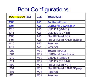
Is this configured via PU/PD on the OSM or via Fuses? Maybe I get it wrong, but according to the datasheet, the iMX93 BootMode 1,2 and 3 Pins are pulled down on the OSM with 10k resulting in a default iMX93 BootMode=000x. The last bit is controlled via FORCE_RECOVERY, but I don’t understand how the BootMode=0010 (eMMC) can be default?
However, maybe you could give me an advice, how UART_CON_TX and UART_C_TX shall be wired on the carrier board to get eMMC mode.
And another question came up regarding CARRIER_PWR_EN.
The datasheet describes it as an open-drain circuit, whereas the OSM specification defines it as a 1.8 V CMOS output.
Does the Toradex OSM iMX93 module always drive a defined LOW or HIGH on this signal, or is it necessary to place an PU/PD resistor on the carrier board?
All BOOT_MODE pins are internally pulled down, so the default boot mode is determined by the internal fuses. These fuses are preconfigured to boot from the internal eMMC. While the fuse settings cannot be changed, you can select an alternative boot mode by using the BOOT_MODE[3:0] module pins.
However, could you please advise on how the UART_CON_TX and UART_C_TX signals should be wired on the carrier board to ensure proper eMMC boot mode operation?*
For eMMC boot, you can leave all BOOT_MODE pins floating or pulled down during power-on. After the boot process is complete, these pins can be reused as regular interface pins (e.g., UART,SPI, GPIO etc).
Does the Toradex OSM i.MX 93 module always drive a defined LOW or HIGH level on the CARRIER_PWR_EN signal, or is an external pull-up/pull-down resistor required on the carrier board?
A pull-up resistor is already populated on the module, so you can treat this pin as a standard push-pull 1.8V output. No external pull-up or pull-down resistor is necessary on the carrier board.