

I want to connect the OBDII interface from a vehicle to an Ixora carrier board. The popular protocols are ISO 15765-4(CAN), 14230-4(UART), ISO 9141-2(UART), SAE J1850 (Pulse Width Modulation) and SAE J1850(Variable Pulse Width). With each pin having its own protocol. Since the Ixora carrier board has CAN, UART, and Pulse Width Modulation. Can I plug the interface directly into the respective pins on the OBDII port and work? Do I need to configure the device tree to get these to work?
Hi, I’m the Toradex AI Assistant.
I might make mistakes or occasionally get you wrong. Our support team will step in if needed.
OBDII Connection to Ixora Carrier Board
Before providing detailed guidance, I need to clarify your setup to ensure accurate recommendations:
Could you please specify:
- Which Toradex module are you using with the Ixora carrier board? (e.g., Apalis iMX6, Apalis iMX8, etc.)
- Which OS and version are you running? (e.g., Torizon OS 7.2.0, Yocto BSP 6.x, etc.)
You can get this information by running the tdx-info command on your device. More details here: https://developer.toradex.com/software/development-resources/tdx-info/
General Guidance on OBDII Integration
 Important: Direct connection is NOT recommended
You cannot directly connect OBDII signals to the Ixora carrier board pins. Here’s why:
1. Voltage Level and Signal Conditioning
- OBDII protocols operate at 12V automotive voltage levels
- Ixora interfaces expect 3.3V logic levels(1)
- Direct connection would damage your carrier board
2. Required Hardware Interface
You need an OBDII-to-logic-level transceiver that:
- Converts 12V automotive signals to 3.3V logic
- Provides electrical isolation
- Handles protocol-specific signal conditioning
3. Available Interfaces on Ixora
According to the Ixora V1.2 datasheet(1):
CAN Interface (X20 Header):
- 2 CAN 2.0b channels available
- Uses isolated ADM3053BRWZ transceivers
- Pins: CAN1_H, CAN1_L, CAN2_H, CAN2_L(1)
UART Interfaces:
- UART1 (X22): RS232 with full handshaking(1)
- UART2, UART3 (X21): RS232(1)
- UART3, UART4 (X27): TTL level(1)
PWM Outputs (X27 Header):
- PWM1-4 available at 3.3V logic level(1)
4. Device Tree Configuration
Yes, you will need device tree configuration depending on:
- Which interfaces you enable
- Pin multiplexing requirements
- Whether you’re using default or custom configurations
The device tree describes hardware configuration to the operating system(2). For the Ixora carrier board, base device trees are provided, but customization may be needed through device tree overlays(3).
Once you provide your module and OS details, I can give you specific device tree guidance and interface configuration instructions.
Best regards,
Toradex AI Assistant.
Did you like my answer? 

If I answered your question, please tick the “Solution” checkbox.
For follow-up questions to me, please use @ToradexAI in your post.
As the AI noted, you can use the interfaces exposed on the Ixora carrier board, such as CAN, UART, and PWM. However, the electrical levels and physical-layer requirements of the OBD-II interface are different, so additional interface circuitry and voltage translation will be required. In practice, you would need to develop an adapter between the Ixora board and the vehicle.
We can certainly help you with this, but we would first need a clearer description of your intended use case and the range of vehicles you plan to support.
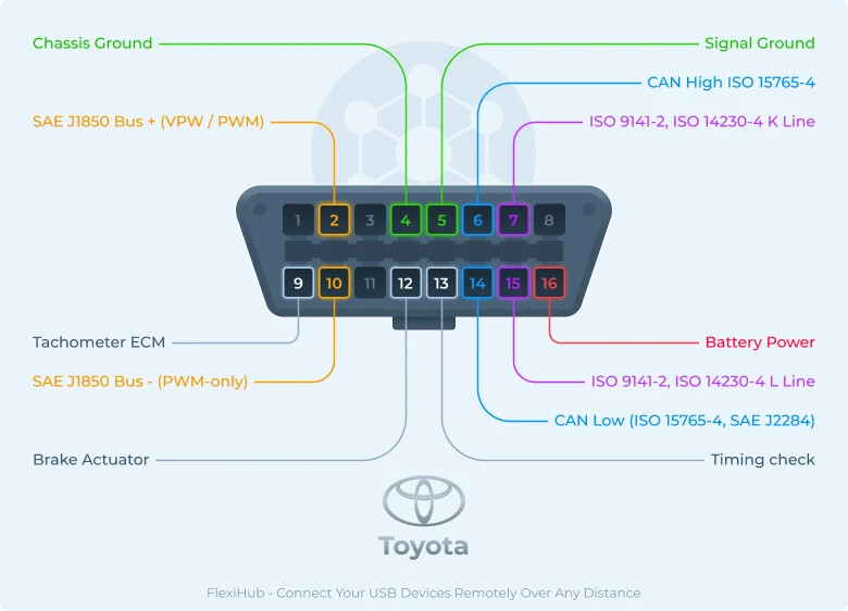
The pinout shown in your picture is the classic OBD-II/J1962 connector assignment. It does not show Ethernet because pins such as 1, 3, 8, 9, 11, 12, and 13 are traditionally manufacturer-specific or discretionary pins.
For modern vehicles, the most important diagnostic interfaces are typically CAN/CAN-FD and, increasingly, Ethernet/DoIP.
UART/K-Line is mainly needed for older vehicles, while SAE J1850 PWM is primarily relevant if you want compatibility with older North American vehicles.
Therefore, if your device is intended mainly for modern vehicles, I would prioritize CAN/CAN-FD and Ethernet, optionally add UART/K-Line for broader backward compatibility, and omit J1850 unless support for older US vehicles is a specific requirement.
The intended use case would be something similar to a diagnostic tool. I would want backward compatibility with most vehicles so I would like to support all the protocols mentioned. I looked into an ELM 327, however these only use usb or bluetooth. I would like a way to use the native CAN, UART & PWM interfaces on the Ixora board instead.
The SAE J1850 PWM protocol uses a two-wire differential bus with nominal 5 V signaling. Connecting it to the Apalis iMX8 requires a J1850-compatible driver/receiver circuit with a 3.3 V logic interface. A simple voltage-level translator is insufficient because the circuit must also provide the correct bus-driving behavior, receiver thresholds, and electrical protection.
SAE J1850 VPW uses a single-wire bus with a nominal high level of approximately 7 V. It likewise requires a suitable bus driver/receiver circuit to interface with 3.3 V logic.
Both J1850 protocols require precise timing for pulse generation, reception, and bus arbitration. For a custom implementation, we recommend handling these functions with an external microcontroller or, potentially, a Cortex-M4 core within the iMX8, subject to peripheral availability and pin routing. This requires real-time firmware; the standard PWM peripheral alone does not implement J1850.
The iXora board already includes two CAN transceivers, so one CAN channel can be connected to the corresponding CAN pins on the OBD-II connector. Check the grounding, protection, and termination configuration: a diagnostic tool connected to an already terminated vehicle CAN bus should not add another 120 Ω termination. The application will also need the appropriate diagnostic software stack, including ISO-TP.
For UART, iXora exposes RS-232 interfaces on X21/X22 and 3.3 V logic-level UART interfaces on X27. RS-232 uses bipolar signaling, whereas the logic-level UART uses approximately 0–3.3 V. Both provide separate transmit and receive signals.
In contrast, the K-line used by ISO 9141-2 and ISO 14230-4 is a single-wire, bidirectional, half-duplex bus. It idles near vehicle battery voltage—typically around 12 V—and is driven low for signaling. Therefore, an automotive K-line transceiver is required between the logic-level UART and the vehicle. This transceiver handles both the electrical conversion and the connection of separate UART TX/RX signals to the shared K-line. Its logic interface must be compatible with 3.3 V operation.
K-line initialization, timing, and protocol handling still need to be implemented in software or firmware. Some older vehicles also require an L-line driver for initialization.