Technical Support queries:
I am not able to see response of cansend on CAN , for COM communication setup fallowing steps from below ink 
How to Use CAN on TorizonCore (toradex.cn)
My can0 interface is enable and showing up but once i execute cansend command not able to see the response on CAN.
Greetings @akshay.singh,
Could you describe your CAN setup/wiring in more detail. Also have you added terminator resistors to your CAN setup? As detailed in this other post: Is there any hardware setting to enable CAN_Rx, CAN_Tx pins on eval board?
Best Regards,
Jeremias
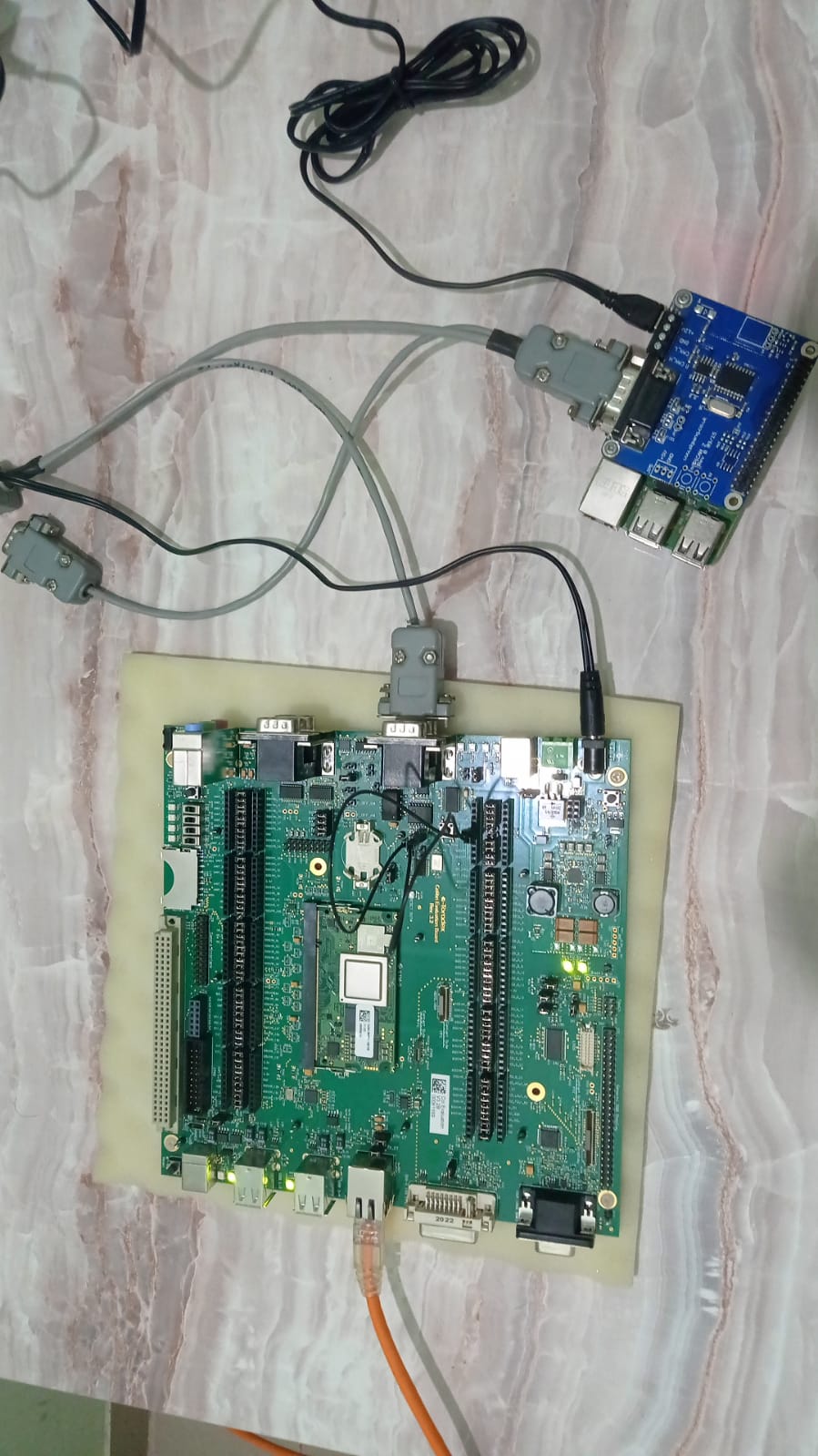
For jumper setting for CAN below is my hardware setting:
**
For CAN Testing on the Toradex Colibri Board we removed the jumpers on JP4 and JP5 (CAN RX/TX). This disconnects the CAN-SPI hardware from the transceiver. Then to use the FlexCAN output, connect SODIMM_55 (on the X9 header) to X38 (side marked TX) and SODIMM_63 (on the X9 header) to X38 (side marked RX).
Along with that remove the jumpers for those SODIMM pins (55 and 63) from the X8 header.
we did above hardware setup for can0 connection and then fallow the software setup steps from toradex link mentioned in my post.
please find my attached h/w setup pic for your reference.
To clarify, do you or do you not have terminating resistors in your setup? It’s hard to tell from the picture but I don’t see any resistors.
Best Regards,
Jeremias
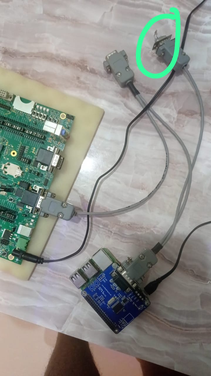
yes ,i am using using terminating resistor in my setup , PFA scrrenshot for your ref.
Based on your connections you are trying to test the on-module CAN interface with SODIMM pins 55 & 63 correct?
Have you enabled this on-module CAN interface in the device tree? I believe it’s not enabled by default.
Best Regards,
Jeremias
i am using default OS provided by board , and yes i am trying CAN interface with SODIMM pins 55 & 63 and i didn’t enable above setting , Could you please provide me the steps to enable this on-module CAN interface in the device tree specific for mentioned setting pin setting.
Below is jumper setting done for above :
CAN Test
For CAN Testing on the Toradex Colibri Board you will want to remove the jumpers on JP4 and JP5 (CAN RX/TX). This disconnects the CAN-SPI hardware from the transceiver. Then to use the FlexCAN output, connect SODIMM_55 (on the X9 header) to X38 (side marked TX) and SODIMM_63 (on the X9 header) to X38 (side marked RX).
Along with that remove the jumpers for those SODIMM pins (55 and 63) from the X8 header
Could you please provide me the steps to enable this on-module CAN interface in the device tree specific for mentioned setting pin setting.
In the device tree the CAN interface for SODIMM 55 & 63 is represented by node flexcan2 as seen here in the source: imx8x-colibri.dtsi « freescale « dts « boot « arm64 « arch - linux-toradex.git - Linux kernel for Apalis, Colibri and Verdin modules
All you would need to do is either modify the device tree or create an overlay that sets this node to enabled with the status = "okay"; field. You can apply overlays or device tree changes using TorizonCore Builder as detailed in this article here: Device Tree Overlays on Torizon | Toradex Developer Center
Best Regards,
Jeremias
I am trying below approch to enabled this on-module CAN interface in the device tree :
Approach 2: Applying Device Tree Overlays to an Image Directly on the Device
but i am not sure where i need to create .dts file , how to build it to create .dtbo files which is going to add in overlays.txt file , could you please provide me the path where we create and build .dts file .
I believe you’re referencing the wrong section of the article. That section is about applying overlays that are already pre-provided by Toradex. Instead for creating a custom overlay, which is what you have to do in this case, you want to look at the approaches under the section " Development and Production: Using TorizonCore Builder".
Best Regards,
Jeremias