Hello,
We are moving away from our current Display due to availability and shipment dates.
We are testing different alternatives to reach for the most efficient.
One of these alternatives could be the final choice but we are experiencing issues: the colours are rendered different and all the vertical lines are “doubled”.
I assume there is something we can try related to the display driver registry but I would like to ask your help in narrowing down all the possible tests we can do by changing registry key values.
Current original display (working fine):
Ampire AM-800480STMQW-A1_DS_001
Datasheet:
AM-800480STMQW-A1_DS_001.pdf (1.2 MB)
Photo:
New alternative display:
AUO G070VTN01.0-AUO
Datasheet:
G070VTN01.0-AUO.pdf (958.4 KB)
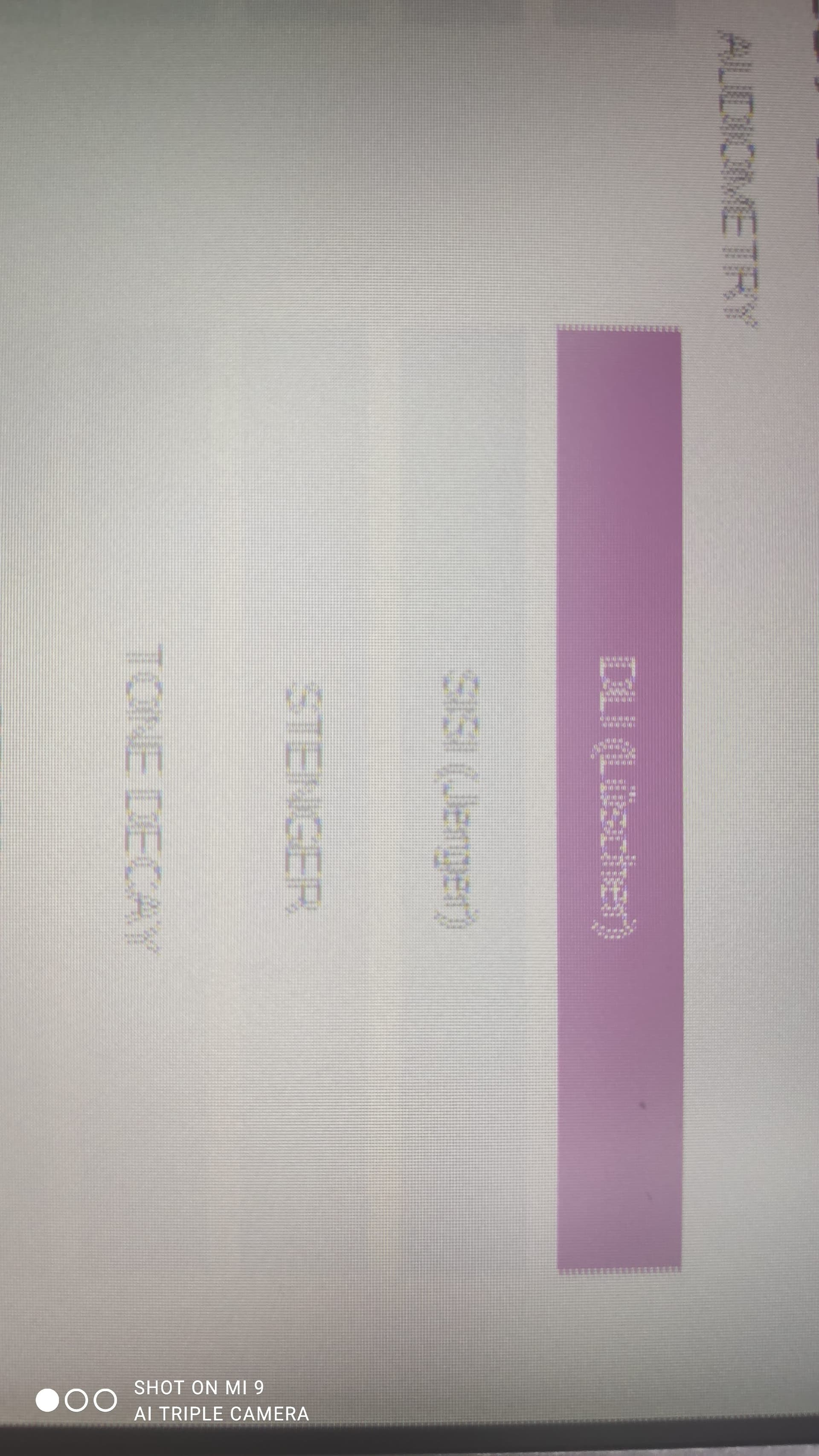
Photo:
(no, it is not a blurred photo).
In the WinCE6 image we use on all our devices, we have the following driver registry:
Display_VF61.reg (1.4 KB)
And since the UseSplashSetting is set to 1, here you can see also the ss config block as well:
SplashScreenConfigBlock.txt (1.9 KB)
If you have any additional suggestions whatsoever feel free to share it.
Thank you in advance for your help.
Colibri VF61 256MB IT V1.2B
Custom Board
WinCE6 BSP 1.5
Hi @EnricoPompeiani
Colibri module has no native LVDS interfaces but both displays have LVDS interface only. So it’s important to know how your custom board translate parallel RGB to LVDS. Then the “old” display has only 3 LVDS data input pairs while the “new” display has 4 LVDS data input pairs, So it’s important to know how exactly display was connected to LVDS converter. Also your “new” display has a additional interface signal “sel68” to control BPP. Where this signal is connected?
Most Likely you don’t need to adjust registry but rather configure correctly your LVDS converter (if possible) and properly set “sel68” signal level.
Could this be an interlaced/non-interlaced configuration issue?
I don’t think so. Details about your LVDS converter and how screens was/is connected are needed to get a concrete answer.
Hello,
I now have learned what the technical details in your answers mean (I was a bit ignorant of it), and I can tell you how my colleagues worked to adapt the wiring of the new display:
- First of all, they swapped the wiring to adapt to the pins configuration of the new display.
- Then they set up the sel68 (pin17, please refer to page 16 of new display datasheet) to be NC.
- They also tried Low (8bits) just out of curiosity,
- But they didn’t try setting it as High (3.3V), although the datasheet says High = same as NC;
- As I wrote, they are setting the PINs 19 and 20 (4th pair of LVDS data) floated, as they “must be”
- Please note that even if it does the trick, it is most likely to solve only the colour issue, not the vertical lines issue.
- Finally, The P-RGB / LVDS interface was already implemented before, to use the old display, so atm I don’t really know much about it.
- They also have performed many tests on slightly different configurations already, so I believe if there is anything yet to be done, is on my side.
I understand this is not very much technical details to work with, but as a company, We have a dedicated hardware designer that manages these issues.
Because I am still required to give the registries a try, please trust them on this topic and just help me by pointing out the registries that are most likely to have an effect.
If you deem it necessary, I will then ask them to provide more detailed information later.
Thank
Actually, scratch all that.
After a few tries, I found out the B.L.W. registry key works just fine if changed from 48 (our previous value) to 128.
Even though I don’t really know why’s that, I will take it.
1 Like
Thank you for the update. Glad your problem was solved.