I have been trying to find information how do management pins function on Toradax SMARC iMX8M Plus Module. The list of pins I am interested in is specified bellow:
Watchdog pin(chapter 3.19 in SMARC 2.2 Specification)
WDT_TIME_OUT#
Management pins (chapter 3.21 in SMARC 2.2 Specification)
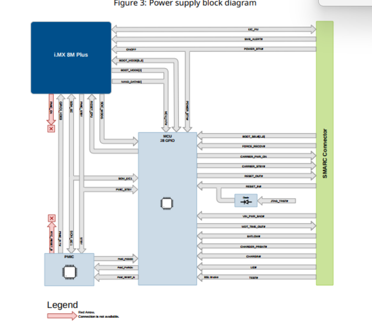
Since I can not find any info about this MCU in datasheet, I am assuming that this MCU runs some proprietary firmware. So I guess there should be documentation explaining how exactly the MCU drives all the before mentioned signals.
I might make mistakes or occasionally get you wrong. Our support team will step in if needed.
Based on the SMARC iMX8M Plus datasheet, the management MCU handles several control signals as you’ve observed in the block diagram. Here’s what the documentation reveals about these pins:
Pin Assignments and MCU Control
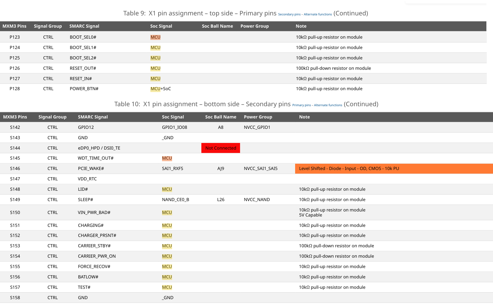
The datasheet confirms that many of the management pins you’ve listed are indeed controlled by an MCU on the module(1). According to the pin assignment tables:
Boot Select Pins (MCU-controlled):
BOOT_SEL0# (P123) - 10kΩ pull-up resistor on module(1)
BOOT_SEL1# (P124) - 10kΩ pull-up resistor on module(1)
BOOT_SEL2# (P125) - 10kΩ pull-up resistor on module(1)
FORCE_RECOV# (S155) - 10kΩ pull-up resistor on module(2)
Management Pins (MCU-controlled):
RESET_OUT# (P126) - 100kΩ pull-down resistor on module(1)
RESET_IN# (P127) - 10kΩ pull-up resistor on module(1)
POWER_BTN# (P128) - 10kΩ pull-up resistor on module(1)
SLEEP# (S149) - 10kΩ pull-up resistor on module(2)
VIN_PWR_BAD# (S150) - 10kΩ pull-up resistor on module(2)
CHARGING# (S151) - 10kΩ pull-up resistor on module(2)
CHARGER_PRSNT# (S152) - 10kΩ pull-up resistor on module(2)
CARRIER_STBY# (S153) - 100kΩ pull-down resistor on module(2)
CARRIER_PWR_ON (S154) - 100kΩ pull-down resistor on module(2)
BATLOW# (S156) - 10kΩ pull-up resistor on module(2)
Unfortunately, the current SMARC iMX8M Plus datasheet does not provide detailed documentation about the MCU firmware behavior or how it specifically manages these signals. The datasheet notes and pull-up/pull-down resistor values indicate MCU control, but the specific firmware logic is not documented in the available sources.
For detailed information about how the MCU firmware handles these management signals, I recommend visiting the Toradex Community or GitHub to inquire about MCU firmware documentation or request additional technical details from Toradex support.
Best regards,
Toradex AI Assistant.
Did you like my answer?
If I answered your question, please tick the “Solution” checkbox.
For follow-up questions to me, please use @ToradexAI in your post.
Yes, some management pins on the Toradex SMARC i.MX8M Plus module are controlled by the onboard MCU, while others are controlled by the i.MX8M Plus SoC, as you can see in the module’s datasheet (Tables 9–10).
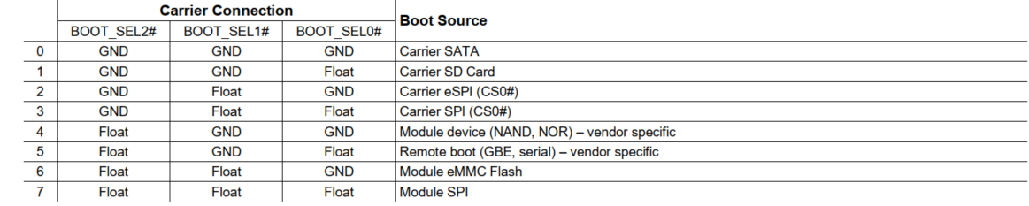
thanks for quick response. SMARC standard is strict in some cases and vauge in others. So if MCU runs proprietary firmware, than I need more clarification. If we begin with Boot Pins. SMARC standard specifies 3 boot selection pins(SMAR Specs 2.2):
I’m taking this over from Alex. Your reading is correct and you found a real gap in the datasheet.
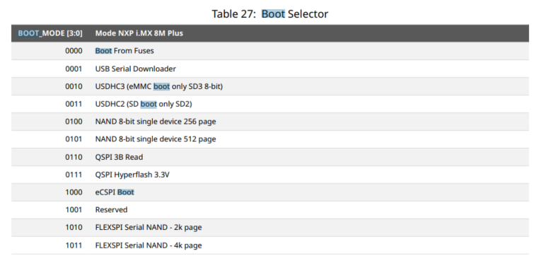
BOOT_SEL and BOOT_MODE are two different buses and the document does not currently say so. Only BOOT_SEL0#, BOOT_SEL1# and BOOT_SEL2# (P123, P124, P125) reach the X1 connector, each with a 10 kΩ pull up on the module. BOOT_MODE[3:0] is internal: it is what the on module Cortex-M MCU drives into the i.MX 8M Plus after interpreting your BOOT_SEL setting, and it is not accessible from the carrier board. The “BOOT_SEL[3:0]” wording in Section 5.7.1 is a typo, and Table 27 lists the SoC boot mode values instead of the SMARC BOOT_SEL configurations, which is why the translation reads as a black box.
That translation table is being added to the datasheet now. It will cover the full path you need for a carrier design, from the BOOT_SEL dip switch setting on the carrier board to the BOOT_MODE value the SoC actually sees, so you can pick a boot source without reverse engineering the MCU behaviour. I will post here when the revised document is published.
On BOOT_SEL[2:0] = 000, SATA is not routed on this module, so that combination has no valid target. The boot sources we validate are the carrier SD card (SDIO, USDHC2) and the on module eMMC (USDHC3). Other SoC boot modes may be reachable through the MCU translation but are not guaranteed. If your design depends on remote boot over GBE or serial, tell me and I will confirm that case specifically.
For your carrier, route all three BOOT_SEL pins to a dip switch or jumpers the way our SMARC Development Board does, rather than hard strapping them. That keeps every combination open once the mapping is published and costs nothing in layout.
FORCE_RECOV# (S155, 10 kΩ pull up) also goes to the MCU, which puts the SoC into USB serial downloader mode, the recovery mode used by the Toradex Easy Installer and uuu. It is sampled during the power up sequence, so it has to be low before the reset is released, not after the module has booted. Keep the USB1 interface accessible on the carrier, since recovery runs over it.