Hello Toradex team,
I hope you are all doing great! And thank you for your support.
Hardware:
uname:
- Linux 0146230000 5.15.148-6.6.1+git.23a8e831749d #1-TorizonCore SMP PREEMPT Thu Feb 29 20:25:21 UTC 2024 aarch64 aarch64 aarch64 GNU/Linux
Images tested:
- torizon-core-docker-verdin-imx8mp-Tezi_6.6.1+build.14.tar (STABLE Release)
Guest OS:
- macOS (M1 Pro ARM64)
- Linux ubuntu (VM x86_64)
Issue:
We have a small issue regarding the LVDS display. So we have 2 models of displays (450 and 1000 cd/m² ).
We have been using the 450 for over a year now without any issue! For the 1000 (that needs more power) we change the length of the soft start (change the capacitor) and we realize that sometimes the LVDS doesn’t start and nothing is showed on the display. We measure the current and we have the appropriate 5V, so we don’t think that its an hardware issue.
So more information, related to the hardware: the LVDS_ENABLE GPIO is located on a I/O expander connected to i2c.
What we think is that the booting order is not deterministic and sometimes that LVDS_ENABLE is not set to 1 before the LVDS module start. Or the current is not enough and it fails to start the module.
I have a few questions for you:
- is-it possible to track down the starting process of each hardware individually and verify the order ? And possibly change it through uboot ?
- is-it possible to restart the LVDS module if something went wrong ?
Just for information, restarting the device fix the issue, because all the power-supply are correctly charged.
I linked the device-tree for the LVDS:
panel_lvds: panel-lvds {
compatible = "panel-lvds";
backlight = <&backlight>;
power-supply = <®_5p0v>;
rotation = <270>;
data-mapping = "vesa-24";
height-mm = <528>;
width-mm = <297>;
status = "okay";
panel-timing {
clock-frequency = <148500000>;
hactive = <1920>;
hback-porch = <1>;
hfront-porch = <129>;
hsync-len = <10>;
hsync-active = <0>;
vactive = <1080>;
vback-porch = <1>;
vfront-porch = <34>;
vsync-len = <10>;
vsync-active = <0>;
de-active = <1>;
pixelclk-active = <1>;
};
I hope you will be able to help us.
Best regards,
M
Hi, I’m the Toradex AI Assistant. I’m in early beta, and I would appreciate your feedback.
The Toradex Support team will follow up with you shortly!
Did you like my answer?


Hello,
Thank you for reaching out with your detailed query regarding the LVDS display issue on your custom carrier board with the Verdin iMX8M Plus module.
Based on the information provided, it seems like the issue might be related to the timing of the LVDS_ENABLE signal, especially considering the additional power requirements of the 1000 cd/m² display model. Let’s address your questions directly:
-
Tracking down and modifying the hardware initialization order through U-Boot:
- It is indeed possible to track and modify the initialization order of hardware components through U-Boot. This can be achieved by customizing the U-Boot environment and scripts. Specifically, you can modify the board initialization code in U-Boot to ensure that the
LVDS_ENABLE GPIO is set to the desired state before the rest of the system starts up. This might involve editing the board-specific initialization files in the U-Boot source code and recompiling U-Boot for your device.
-
Restarting the LVDS module if something goes wrong:
- Restarting the LVDS module programmatically can be a bit more complex, as it depends on how the LVDS driver is implemented in the Linux kernel. However, you can control the
LVDS_ENABLE GPIO from userspace (e.g., through the sysfs interface or a custom application) to disable and re-enable the LVDS display. This approach allows you to reset the LVDS module by toggling the enable GPIO, essentially simulating a manual restart of the module. This can be done at any point after the system has booted, including as part of a startup script if the initial initialization fails.
For the first approach, you would need to dive into the U-Boot source code for your board, locate the initialization sequence, and modify it to ensure the LVDS_ENABLE GPIO is set early enough. This might require a good understanding of U-Boot’s initialization process for your specific hardware.
For the second approach, controlling the GPIO from userspace can be done by identifying the correct GPIO number for LVDS_ENABLE and using the echo command to write to the corresponding files in /sys/class/gpio/ to export the GPIO, set its direction, and write values to it.
Given the complexity of these solutions, especially modifying U-Boot, it’s important to proceed with caution and thoroughly test any changes in a controlled environment to avoid unintended consequences.
Best regards,
Toradex AI Assistant
Please, also check if these links can help you solve your problem:
Display Output, Resolution and Timings (Linux) | Toradex Developer Center.
The dmesg command displays the kernel ring buffer messages. This includes logs of hardware initialization and driver loading.
You can also use journalctl to view logs related to hardware initialization.
The iMX8M Plus LVDS driver/interface does not check if an LVDS display is initialized or even present; it starts sending pixel data as soon as it is loaded, so it is unlikely that restarting the driver will help.
It is more likely that the display itself went into a wrong state if the LVDS_ENABLE or some other control signal(s) is(are) in the wrong state when the display receives the required power supply voltage. Additionally, the internal display controller may hang if the supply voltage is raised too slowly.
Can you share the display datasheet/reference manual?
Hello @alex.tx,
For what I can see on the dmesg, the i2c is fire before the LVDS.
You can find the datasheet for the display here: 1000 cd_m2 - TFT-LCD Preliminary Specification G238HCJ-LH1 Ver 1.1.pdf (1.9 MB)
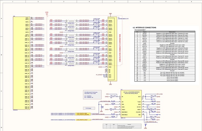
I joined a screenshot of our schematic related to the LVDS:
I hope you will be able to help us.
Best regards,
M
Neither the schematic snippet you provided nor the display datasheet has any reference to I2C. I believe it is related to the touch controller, but the display and touch controller are two independent entities and can be initialized in any order.
Your display requires 24V for the backlight. Could you double-check with a voltmeter or an oscilloscope if the backlight power is within the 21.6V - 16.4V range when no image is shown?
Hello @alex.tx,
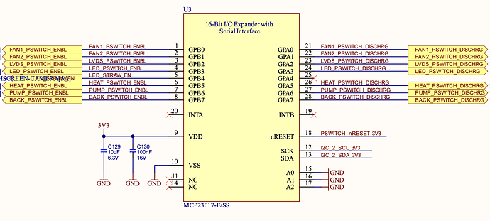
The I2C is use for the I/O Expander:
The backlight of the display works perfectly, I can see the display on but nothing display on the screen (black screen).
We measure every point, and we have the appropriate value everywhere (24V, 5V, 3.3V).
While I was looking for a solution online, I found this link. It seems that I’m not the only one facing the issue.
Best regards,
M
Do you know exactly which timings required by your custom display are broken?
Please use an oscilloscope or logic analyzer and collect the timings of display VCC, LVDS_PSWITCHC_ENBL, and LVDS_PSWITCHC_DSCRG signals for both cases when the display works and when it doesn’t. You can also double-check if the LVDS clock and data lines are still active when there is no image on the display.
1 Like
Hello @alex.tx,
Quick update on this problem.
We decide to update the schematic by changing the wire for LVDS_ENABLE with a pull to 3.3V in place of the GND. We will always use the LVDS display with our product so it make more sense that way.
Thank you for your help.
Best regards,
M

