I have a custom APALIS IMX8 carrier board on which I use the LPSPI1 port connected to pins 311,315, 317, 319. With the 5.1 BSP (Linux apalis-imx8 5.4.47-5.1.0-devel+git.d376697f9559 #1 SMP PREEMPT Wed Oct 21 13:19:41 UTC 2020 aarch64 aarch64 aarch64 GNU/Linux) I am having trouble getting this port to operate. It looks like the SCLK is not being generated for the port. I have used the port in the past with previous versions of the BSP. To test the port I have moved back to the IXORA carrier board and replicated the problem. I do not have an SPI device connected to the IXORA board and am simply measuring the port outputs with a scope.
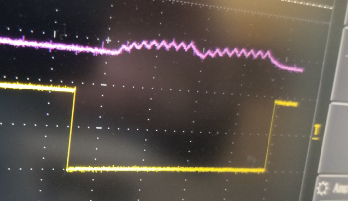
I have attempted to modify the DTB file to enable the port. Using the modified DTB file I can enable the port and spidev2.0 is enumerated in /dev. When I write to the spidev2.0 (using a python script), I can see the data out on the SDO pin [Ixora pin 5 on X16]. I can see the CS0 toggle [Ixora pin 3 on X16]. The clock line does NOT generate a valid clock. I see one small voltage spike and a discharge when I attempt to read from the SPI port. The voltage spike is ~250mv and discharges within 25us. I do not have anything connected to the port except the oscilloscope.
Here are the device tree changes that I have made:
diff --git a/arch/arm64/boot/dts/freescale/imx8qm-apalis-ixora-v1.1.dtsi b/arch/arm64/boot/dts/freescale/imx8qm-apalis-ixora-v1.1.dtsi
index 7d293fa860d6..9525482a1a7e 100644
--- a/arch/arm64/boot/dts/freescale/imx8qm-apalis-ixora-v1.1.dtsi
+++ b/arch/arm64/boot/dts/freescale/imx8qm-apalis-ixora-v1.1.dtsi
@@ -41,13 +41,34 @@
 		regulator-name = "VCC_USBH(2|4)";
 	};
 };
+&dma_subsys{
+	lpspi1: spi@5a010000 {
+		compatible = "fsl,imx7ulp-spi";
+		reg = <0x5a010000 0x10000>;
+		#address-cells = <1>;
+		#size-cells = <0>;
+		interrupts = <GIC_SPI 217 IRQ_TYPE_LEVEL_HIGH>;
+		interrupt-parent = <&gic>;
+		clocks = <&spi1_lpcg 0>,
+			 <&spi1_lpcg 1>;
+		clock-names = "per", "ipg";
+		assigned-clocks = <&clk IMX_SC_R_SPI_1 IMX_SC_PM_CLK_PER>;
+		assigned-clock-rates = <60000000>;
+		power-domains = <&pd IMX_SC_R_SPI_1>;
+		dma-names = "tx","rx";
+		dmas = <&edma2 3 0 0>, <&edma2 2 0 1>;
+		status = "disabled";
+	};
+
+
+};

 &adc0 {
-	status = "okay";
+	status = "disabled";
 };

 &adc1 {
-	status = "okay";
+	status = "disabled";
 };

 &amix {
@@ -307,20 +328,29 @@
 		    <&pinctrl_qspi1a_gpios>, <&pinctrl_sata1_act>,
 		    <&pinctrl_sim0_gpios>, <&pinctrl_usdhc1_gpios>,
 		    <&pinctrl_uart24_forceoff>;
+	apalis-imx8qm {
+		pinctrl_leds_ixora: ledsixoragrp {
+			fsl,pins = <
+				IMX8QM_USDHC2_DATA1_LSIO_GPIO5_IO27 			0x41 /* LED_4_GREEN */
+				IMX8QM_USDHC2_DATA3_LSIO_GPIO5_IO29 			0x41 /* LED_4_RED */
+				IMX8QM_USDHC1_DATA5_LSIO_GPIO5_IO20 			0x41 /* LED_5_GREEN */
+				IMX8QM_USDHC1_DATA6_LSIO_GPIO5_IO21 			0x41 /* LED_5_RED */
+			>;
+		};

-	pinctrl_leds_ixora: ledsixoragrp {
-		fsl,pins = <
-			IMX8QM_USDHC2_DATA1_LSIO_GPIO5_IO27 			0x41 /* LED_4_GREEN */
-			IMX8QM_USDHC2_DATA3_LSIO_GPIO5_IO29 			0x41 /* LED_4_RED */
-			IMX8QM_USDHC1_DATA5_LSIO_GPIO5_IO20 			0x41 /* LED_5_GREEN */
-			IMX8QM_USDHC1_DATA6_LSIO_GPIO5_IO21 			0x41 /* LED_5_RED */
-		>;
-	};
-
-	pinctrl_uart24_forceoff: uart24forceoffgrp {
-		fsl,pins = <
-			IMX8QM_USDHC2_CMD_LSIO_GPIO5_IO25 			0x21
-		>;
+		pinctrl_uart24_forceoff: uart24forceoffgrp {
+			fsl,pins = <
+				IMX8QM_USDHC2_CMD_LSIO_GPIO5_IO25 			0x21
+			>;
+		};
+		pinctrl_lpspi1: lpspi1grp {
+			fsl,pins = <
+				IMX8QM_ADC_IN3_DMA_SPI1_SCK		0x0600004c
+				IMX8QM_ADC_IN4_DMA_SPI1_SDO		0x0600004c
+				IMX8QM_ADC_IN5_DMA_SPI1_SDI		0x0600004c
+				IMX8QM_ADC_IN6_LSIO_GPIO3_IO24		0x0600004c
+			>;
+		};
 	};
 };

@@ -353,7 +383,21 @@
 &lpspi0 {
 	status = "okay";
 };
-
+&lpspi1 {
+	pinctrl-names = "default";
+	pinctrl-0 = <&pinctrl_lpspi1>;
+	#address-cells = <1>;
+	#size-cells = <0>;
+	cs-gpios = <&lsio_gpio3 24 GPIO_ACTIVE_LOW>;
+
+
+	status = "okay";
+	spidev2: spi@0 {
+		compatible = "toradex,evalspi";
+		reg = <0>;
+		spi-max-frequency = <4000000>;
+	};
+};
 /* Apalis SPI2 */
 &lpspi2 {
 	status = "okay";
diff --git a/arch/arm64/boot/dts/freescale/imx8qm-ss-dma.dtsi b/arch/arm64/boot/dts/freescale/imx8qm-ss-dma.dtsi
index b9b364b0ecc8..a1f329efcfa7 100644
--- a/arch/arm64/boot/dts/freescale/imx8qm-ss-dma.dtsi
+++ b/arch/arm64/boot/dts/freescale/imx8qm-ss-dma.dtsi
@@ -70,6 +70,10 @@
 &edma2 {
 	reg = <0x5a200000 0x10000>, /* channel0 LPSPI0 rx */
 	      <0x5a210000 0x10000>, /* channel1 LPSPI0 tx */
+	      <0x5a220000 0x10000>, /* channel2 LPSPI1 rx */
+	      <0x5a230000 0x10000>, /* channel3 LPSPI1 tx */
+	      <0x5a240000 0x10000>, /* channel4 LPSPI2 rx */
+	      <0x5a250000 0x10000>, /* channel5 LPSPI2 tx */
 	      <0x5a260000 0x10000>, /* channel6 LPSPI3 rx */
 	      <0x5a270000 0x10000>, /* channel7 LPSPI3 tx */
 	      <0x5a2c0000 0x10000>, /* channel12 UART0 rx */
@@ -83,9 +87,13 @@
 	      <0x5a340000 0x10000>, /* channel20 UART4 rx */
 	      <0x5a350000 0x10000>; /* channel21 UART4 tx */
 	#dma-cells = <3>;
-	dma-channels = <14>;
+	dma-channels = <18>;
 	interrupts = <GIC_SPI 416 IRQ_TYPE_LEVEL_HIGH>,
 		     <GIC_SPI 417 IRQ_TYPE_LEVEL_HIGH>,
+		     <GIC_SPI 418 IRQ_TYPE_LEVEL_HIGH>,
+		     <GIC_SPI 419 IRQ_TYPE_LEVEL_HIGH>,
+		     <GIC_SPI 420 IRQ_TYPE_LEVEL_HIGH>,
+		     <GIC_SPI 421 IRQ_TYPE_LEVEL_HIGH>,
 		     <GIC_SPI 422 IRQ_TYPE_LEVEL_HIGH>,
 		     <GIC_SPI 423 IRQ_TYPE_LEVEL_HIGH>,
 		     <GIC_SPI 434 IRQ_TYPE_LEVEL_HIGH>,
@@ -99,6 +107,8 @@
 		     <GIC_SPI 442 IRQ_TYPE_LEVEL_HIGH>,
 		     <GIC_SPI 443 IRQ_TYPE_LEVEL_HIGH>;
 	interrupt-names = "edma0-chan0-rx", "edma0-chan1-tx",
+			  "edma0-chan2-rx", "edma0-chan3-tx",
+			  "edma0-chan4-rx", "edma0-chan5-tx",
 			  "edma0-chan6-rx", "edma0-chan7-tx",
 			  "edma0-chan12-rx", "edma0-chan13-tx",
 			  "edma0-chan14-rx", "edma0-chan15-tx",
@@ -107,6 +117,10 @@
 			  "edma0-chan20-rx", "edma0-chan21-tx";
 	power-domains = <&pd IMX_SC_R_DMA_0_CH0>,
 			<&pd IMX_SC_R_DMA_0_CH1>,
+			<&pd IMX_SC_R_DMA_0_CH2>,
+			<&pd IMX_SC_R_DMA_0_CH3>,
+			<&pd IMX_SC_R_DMA_0_CH4>,
+			<&pd IMX_SC_R_DMA_0_CH5>,
 			<&pd IMX_SC_R_DMA_0_CH6>,
 			<&pd IMX_SC_R_DMA_0_CH7>,
 			<&pd IMX_SC_R_DMA_0_CH12>,
@@ -120,6 +134,8 @@
 			<&pd IMX_SC_R_DMA_0_CH20>,
 			<&pd IMX_SC_R_DMA_0_CH21>;
 	power-domain-names = "edma0-chan0", "edma0-chan1",
+			     "edma0-chan2", "edma0-chan3",
+			     "edma0-chan4", "edma0-chan5",
 			     "edma0-chan6", "edma0-chan7",
 			     "edma0-chan12", "edma0-chan13",
 			     "edma0-chan14", "edma0-chan15",
The changed that I made to imx8qm-ss-dma.dtsi are based on the changes made by NXP on there 5.4.47-5.2.0 branch.
Has anyone else attempted to use LPSPI1 with 5.1 on the IMX8QM?
What am I missing?
Thanks
-Todd