Issue:
We are reviewing our carrier board one more time before launching the next production.
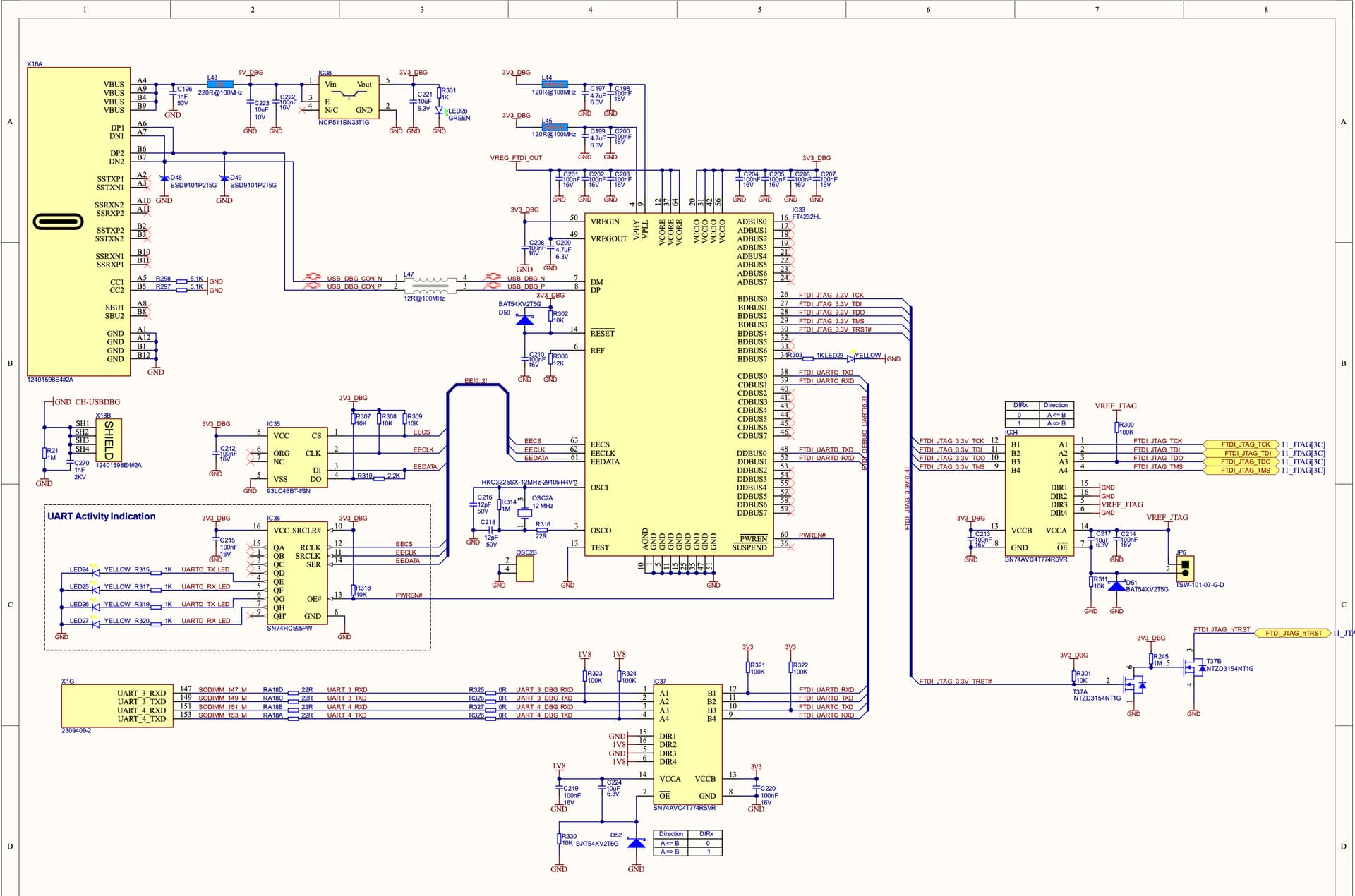
And while I was checking it, I came accross on IC that doesn’t seems necessary for me but I could be wrong, so my question is: do we need to fit the IC34 on our carrier board or it’s not mandatory as you can see on (the right of) the schematic ?
Our recommended workflow with software does not require the use of JTAG for system bring-up or for debugging the Linux OS/application. However, JTAG can be useful for debugging M core applications. It’s not necessary to route JTAG through a USB-C UART/MPSSE chip. Instead, you can simply install a standard 10-pin header somewhere on the board.
You can entirely omit the use of the FT4232H chip. Please refer to the carrier board design guide for more details. However, we strongly recommend making the USB_1 interface accessible in USB client mode to facilitate module recovery. Additionally, it’s advisable to provide access to UART_3, as it is intended for main OS debug log output and serial console use. To save space and reduce costs, you could opt to install only a header for this purpose. Developers who require this functionality can then use any commercially available TTL to USB serial converter.
If you choose to use the FT4232H IC and wish to keep JTAG signals accessible, then including IC34 is mandatory. This is because the FT4232H operates at 3.3V signal levels, whereas the Verdin module supports only 1.8V levels.
The design of that schematic was intended to simplify the lives of software engineers. It allows them to directly connect the board to their development machine without the hassle of finding the correct USB to Serial adapter. For your production boards, however, such complexity is definitely unnecessary. End users should not have to worry about program debugging, and if a technician needs to collect a boot log or use a serial console, having a header as a solution is perfectly acceptable. Just make sure it’s placed in an accessible location. If UART_4 is not utilized in your design, I recommend opting for a 2.54 mm header as for UART_3. You can leave it unpopulated; if needed in the future (for instance, if some OS image uses it as a debug console), it can be easily soldered on