Hi @edmirsuljicOIM !
I would like to try to explain how the pin muxing works on the device tree (as seems like this kind of explanation will be helpful to you ![]() ).
).
This kind of node that you shared is the gpio controller node. Not the muxing for the pins that are controlled by this gpio controller. You can see this node below as the gpiochip itself, but not its lines.
To set or check the mux of a pin (or a set of pins), you need to look for the iomuxc node. I created a python script that can help to find strings in a set of device tree files: GitHub - griloHBG/find_in_devicetree: A helper to find stuff on a device tree hierarchy. Searches recursively inside included files..
Inside iomuxc, you will find several nodes generally labeled pinctrl_*. These nodes hold the pin muxing setup for several pins and are generally organized by hardware/interface/device usage. For example, all UART1-related pin muxing are listed inside the node labeled pinctrl_uart1.
To find it using find_in_dt:
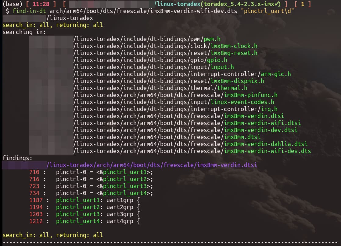
But be aware that the muxing inside these nodes are not actually executing the pin configuration. To make the muxing happen, you need to assign the pinctrl_* label to some pinctrl-# (# is usually a number) property of some node. You can see in the image above that the pinctrl_uart1 label is defined at line 1187 of imx8mm-verdin.dtsi and assigned to the property pinctrl-0 of some (other) node at line 710 of the same file.
To change the mux of some pin, you need to follow the same idea. And, of course, you need to remove/disable the original pin mux (and consequentially the node that its pinctrl-# is assigned to the pinctrl_*). The easiest way to disable the original pin mux is usually to set status = "disabled"; on the node that has the pinctrl-# targeting the pinctrl_* that has your pin.
The pin names in the device tree are defined in a way that the mux function of a pin is simply appended to the pin name, as you can see below.
linux-toradex/arch/arm64/boot/dts/freescale/imx8mm-pinfunc.h
        431 : #define MX8MM_IOMUXC_SAI2_RXFS_SAI2_RX_SYNC                                 0x1B0 0x418 0x000 0x0 0x0
        432 : #define MX8MM_IOMUXC_SAI2_RXFS_SAI5_TX_SYNC                                 0x1B0 0x418 0x4EC 0x1 0x2
        433 : #define MX8MM_IOMUXC_SAI2_RXFS_UART1_TX                                     0x1B0 0x418 0x000 0x4 0x0
        434 : #define MX8MM_IOMUXC_SAI2_RXFS_UART1_RX                                     0x1B0 0x418 0x4F4 0x4 0x2
        435 : #define MX8MM_IOMUXC_SAI2_RXFS_GPIO4_IO21                                   0x1B0 0x418 0x000 0x5 0x0
        436 : #define MX8MM_IOMUXC_SAI2_RXFS_SIM_M_HSIZE0                                 0x1B0 0x418 0x000 0x7 0x0
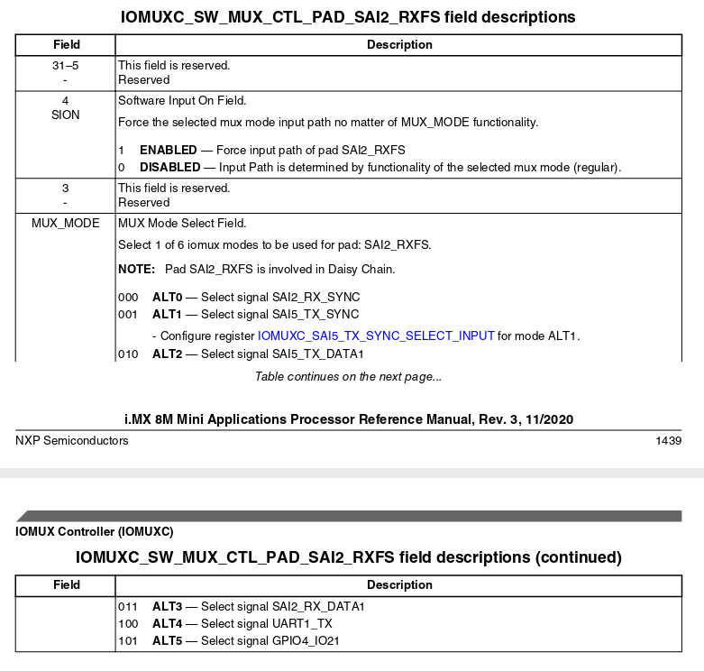
You have the same idea for all pins. So you need to use the pin name and mux in the pinctrl_* as well as the pad configuration for the pin (pull up, pull down, open drain, drive strength…). The pad configuration information you need to get from NXP’s Reference Manual for the SoC you are using. Example from NXP’s Reference Manual for i.MX 8M Mini specifically for pin named SAI2_RXFS:
Please check the How to Customize Device Trees | Toradex Developer Center article for some examples.
Best regards,