Issues with pin mapping

Hello, we are using a custom carrier board with the Verdin imx8mm with a custom device tree.

The following pins are configured to GPIO and these are all set to output pins (to control LEDs).
However we can control these four:
SODIMM-206
SODIMM-208
SODIMM-210
SODIMM-212

But not these four:
SODIMM-137
SODIMM-139
SODIMM-141
SODIMM-143

There is the same behavior on the following pins but they are set as input pins (to control buttons):
These we can control:
SODIMM-216
SODIMM-218
SODIMM-220
SODIMM-222

These we cannot control:
SODIMM-129
SODIMM-131
SODIMM-133
SODIMM-135

If I do a gpioinfo this is the result

gpiochip4 - 32 lines:
        line   0: "SODIMM_131"       unused   input  active-high 
        line   1:      unnamed "CTRL_SLEEP_MOCI#" output active-high [used]
        line   2:  "SODIMM_91"       unused   input  active-high 
        line   3:  "SODIMM_16"       unused   input  active-high 
        line   4:  "SODIMM_15"       unused   input  active-high 
        line   5: "SODIMM_208"       unused  output  active-high 
        line   6: "SODIMM_137"       unused  output  active-high 
        line   7: "SODIMM_139"       unused  output  active-high 
        line   8: "SODIMM_141"       unused  output  active-high 
        line   9: "SODIMM_143"       unused  output  active-high 
        line  10: "SODIMM_196"       unused   input  active-high 
        line  11: "SODIMM_200"       unused   input  active-high 

It looks the same on gpiochip 0 - 3, I just showed this one to reduce text.

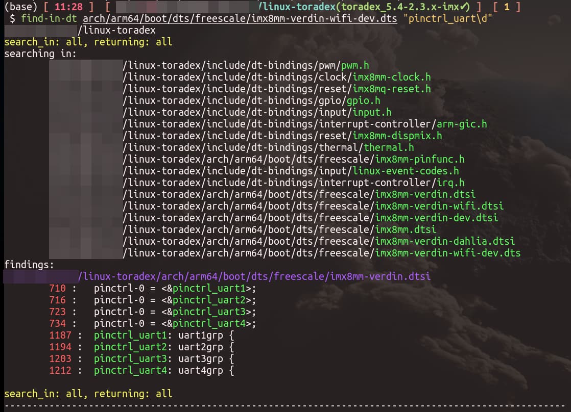
The pattern on the pins that do not work is that they are originally set as UART pins but it is supposed to be changed in the device tree and if I look in gpioinfo they all look the same. I used gpioset to control them.

Here’s part of the device tree for the GPIO (I did not write this device tree so I’m not 100% sure what is happening here).

			gpio@30200000 {
				compatible = "fsl,imx8mm-gpio\0fsl,imx35-gpio";
				reg = <0x30200000 0x10000>;
				interrupts = <0x00 0x40 0x04 0x00 0x41 0x04>;
				clocks = <0x02 0xdf>;
				gpio-controller;
				#gpio-cells = <0x02>;
				interrupt-controller;
				#interrupt-cells = <0x02>;
				gpio-ranges = <0x14 0x00 0x0a 0x1e>;
				gpio-line-names = "SODIMM_216\0SODIMM_19\0\0\0\0\0\0\0SODIMM_220\0SODIMM_222\0\0SODIMM_218\0SODIMM_155\0SODIMM_157\0SODIMM_185\0SODIMM_187";
				phandle = <0x2e>;
			};

			gpio@30210000 {
				compatible = "fsl,imx8mm-gpio\0fsl,imx35-gpio";
				reg = <0x30210000 0x10000>;
				interrupts = <0x00 0x42 0x04 0x00 0x43 0x04>;
				clocks = <0x02 0xe0>;
				gpio-controller;
				#gpio-cells = <0x02>;
				interrupt-controller;
				#interrupt-cells = <0x02>;
				gpio-ranges = <0x14 0x00 0x28 0x15>;
				gpio-line-names = "\0\0\0\0\0\0\0\0\0\0\0\0SODIMM_84\0SODIMM_78\0SODIMM_74\0SODIMM_80\0SODIMM_82\0SODIMM_70\0SODIMM_72";
				phandle = <0x4a>;
			};

			gpio@30220000 {
				compatible = "fsl,imx8mm-gpio\0fsl,imx35-gpio";
				reg = <0x30220000 0x10000>;
				interrupts = <0x00 0x44 0x04 0x00 0x45 0x04>;
				clocks = <0x02 0xe1>;
				gpio-controller;
				#gpio-cells = <0x02>;
				interrupt-controller;
				#interrupt-cells = <0x02>;
				gpio-ranges = <0x14 0x00 0x3d 0x1a>;
				gpio-line-names = "SODIMM_52\0SODIMM_54\0SODIMM_64\0SODIMM_21\0SODIMM_206\0SODIMM_76\0SODIMM_56\0SODIMM_58\0SODIMM_60\0SODIMM_62\0\0\0\0\0SODIMM_66\0SODIMM_17\0\0\0\0SODIMM_244\0SODIMM_250\0SODIMM_48\0SODIMM_44\0SODIMM_42\0SODIMM_46";
				phandle = <0x40>;
			};

			gpio@30230000 {
				compatible = "fsl,imx8mm-gpio\0fsl,imx35-gpio";
				reg = <0x30230000 0x10000>;
				interrupts = <0x00 0x46 0x04 0x00 0x47 0x04>;
				clocks = <0x02 0xe2>;
				gpio-controller;
				#gpio-cells = <0x02>;
				interrupt-controller;
				#interrupt-cells = <0x02>;
				gpio-ranges = <0x14 0x00 0x57 0x20>;
				gpio-line-names = "SODIMM_102\0SODIMM_90\0SODIMM_92\0SODIMM_94\0SODIMM_96\0SODIMM_100\0\0\0\0SODIMM_174\0SODIMM_120\0SODIMM_104\0SODIMM_106\0SODIMM_108\0SODIMM_112\0SODIMM_114\0SODIMM_116\0\0SODIMM_118\0\0SODIMM_88\0SODIMM_149\0SODIMM_147\0SODIMM_36\0SODIMM_32\0SODIMM_30\0SODIMM_34\0SODIMM_38\0SODIMM_252\0SODIMM_133\0SODIMM_135\0SODIMM_129";
				phandle = <0x7b>;
			};

			gpio@30240000 {
				compatible = "fsl,imx8mm-gpio\0fsl,imx35-gpio";
				reg = <0x30240000 0x10000>;
				interrupts = <0x00 0x48 0x04 0x00 0x49 0x04>;
				clocks = <0x02 0xe3>;
				gpio-controller;
				#gpio-cells = <0x02>;
				interrupt-controller;
				#interrupt-cells = <0x02>;
				gpio-ranges = <0x14 0x00 0x77 0x1e>;
				gpio-line-names = "SODIMM_131\0\0SODIMM_91\0SODIMM_16\0SODIMM_15\0SODIMM_208\0SODIMM_137\0SODIMM_139\0SODIMM_141\0SODIMM_143\0SODIMM_196\0SODIMM_200\0SODIMM_198\0SODIMM_202\0\0\0SODIMM_55\0SODIMM_53\0SODIMM_95\0SODIMM_93\0SODIMM_14\0SODIMM_12\0\0\0\0\0SODIMM_210\0SODIMM_212\0SODIMM_151\0SODIMM_153";
				phandle = <0x2d>;

				ctrl_sleep_moci {
					gpio-hog;
					gpios = <0x01 0x00>;
					line-name = "CTRL_SLEEP_MOCI#";
					output-low;
					pinctrl-names = "default";
					pinctrl-0 = <0x15>;
				};
			};

Any ideas?

Hello can you share your Device tree file please?

Best Regards,

Matthias

Double check the pinmux settings for GPIO you can’t control.

imx8mm-verdin-wifi-dahlia.dts (402 Bytes)

I am checking but could you explain the difference between dts and dtsi files? Are they both always used in a configuration? Or could I read about it somewhere?

I noticed that they usually #include dtsi files in the dts files. And I am assuming that my co worker just wrote over everything in the original dts file hence why there are no includes in the current one.

We figured it out. That file is actually a .dtb file that was compiled back to a .dts file, which for obvious reasons, makes it impossible to understand what is wrong.

Hi @edmirsuljicOIM !

I would like to try to explain how the pin muxing works on the device tree (as seems like this kind of explanation will be helpful to you :slight_smile: ).

This kind of node that you shared is the gpio controller node. Not the muxing for the pins that are controlled by this gpio controller. You can see this node below as the gpiochip itself, but not its lines.

To set or check the mux of a pin (or a set of pins), you need to look for the iomuxc node. I created a python script that can help to find strings in a set of device tree files: GitHub - griloHBG/find_in_devicetree: A helper to find stuff on a device tree hierarchy. Searches recursively inside included files..

Inside iomuxc, you will find several nodes generally labeled pinctrl_*. These nodes hold the pin muxing setup for several pins and are generally organized by hardware/interface/device usage. For example, all UART1-related pin muxing are listed inside the node labeled pinctrl_uart1.
To find it using find_in_dt:

But be aware that the muxing inside these nodes are not actually executing the pin configuration. To make the muxing happen, you need to assign the pinctrl_* label to some pinctrl-# (# is usually a number) property of some node. You can see in the image above that the pinctrl_uart1 label is defined at line 1187 of imx8mm-verdin.dtsi and assigned to the property pinctrl-0 of some (other) node at line 710 of the same file.

To change the mux of some pin, you need to follow the same idea. And, of course, you need to remove/disable the original pin mux (and consequentially the node that its pinctrl-# is assigned to the pinctrl_*). The easiest way to disable the original pin mux is usually to set status = "disabled"; on the node that has the pinctrl-# targeting the pinctrl_* that has your pin.

The pin names in the device tree are defined in a way that the mux function of a pin is simply appended to the pin name, as you can see below.

linux-toradex/arch/arm64/boot/dts/freescale/imx8mm-pinfunc.h
        431 : #define MX8MM_IOMUXC_SAI2_RXFS_SAI2_RX_SYNC                                 0x1B0 0x418 0x000 0x0 0x0
        432 : #define MX8MM_IOMUXC_SAI2_RXFS_SAI5_TX_SYNC                                 0x1B0 0x418 0x4EC 0x1 0x2
        433 : #define MX8MM_IOMUXC_SAI2_RXFS_UART1_TX                                     0x1B0 0x418 0x000 0x4 0x0
        434 : #define MX8MM_IOMUXC_SAI2_RXFS_UART1_RX                                     0x1B0 0x418 0x4F4 0x4 0x2
        435 : #define MX8MM_IOMUXC_SAI2_RXFS_GPIO4_IO21                                   0x1B0 0x418 0x000 0x5 0x0
        436 : #define MX8MM_IOMUXC_SAI2_RXFS_SIM_M_HSIZE0                                 0x1B0 0x418 0x000 0x7 0x0

You have the same idea for all pins. So you need to use the pin name and mux in the pinctrl_* as well as the pad configuration for the pin (pull up, pull down, open drain, drive strength…). The pad configuration information you need to get from NXP’s Reference Manual for the SoC you are using. Example from NXP’s Reference Manual for i.MX 8M Mini specifically for pin named SAI2_RXFS:

Please check the How to Customize Device Trees | Toradex Developer Center article for some examples.

Best regards,

Thanks a lot for the explanation. Turns out we needed to disable a couple of the modules and it works now.

Hi @edmirsuljicOIM !

Thanks for the feedback!

Could you please share what you did to make it work for you?

Sharing solutions is always good to help other Community users :slight_smile:

Best regards,
Henrique

So we didn’t disable the UART module in the device tree which is why the GPIO didnt work. It was not more complicated than than actually.

Hi @edmirsuljicOIM !

Thanks for the feedback!

I marked your last message as the solution.

Best regards,
Henrique