iMX8QXP Colibri and CONFIG_POWER_RESET_GPIO for powering off the board

Greetings,
I am making an application based on the Colibri imx8 and evaluation board, I am using Docker and Torizon (very ;-} customer). I got stuck again and need to ask another dumb question.

The application requirements desire the hardware to be able to shutdown completely.

Now I notice the board does not shutdown as supplied, but there is a solution in:

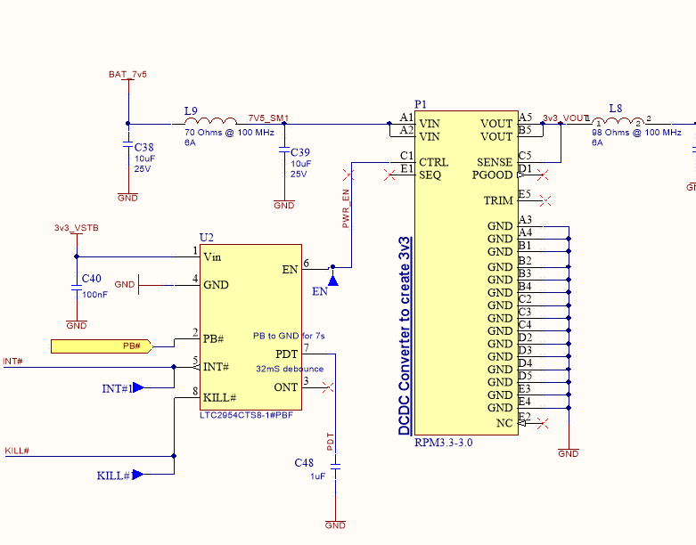
  1. Implementing a GPIO output to FORCE_OFF# that goes low on shutdown and switches off the LTC2954
  2. A driver “gpio-poweroff” does that task, and mux will set the pin so it goes to GND just before shutdown
  3. Switch on a kernel option editor which enables “CONFIG_POWER_RESET_GPIO”.

The first 2 are easy with a wire strap and Torizon and were done in seconds, but then I came a bit unstuck.

Item 3 looks like I need to revert back to OE/Yocto, fish out all of the Torizon sources and run the nconfig menu and then compile the whole distribution just to add this option. I must be wrong, but I cant see how else to do this? Is this only way to enable the CONFIG_POWER_RESET_GPIO option ?

Is there something in Torizoncore-builder that allows me to patch in the kernel option?

All the best!

FatLinux

Greetings @FatLinux,

As of the moment if you want to add additional kernel configs you will indeed need to rebuild the sources and add your config. Unfortunately torizoncore-builder is incapable of this functionality. Since building the kernel like this separately and out of sync with the rest of the image could lead to some strange issues, which we rather avoid.

Let me do this. Let me ask internally if we can just include the CONFIG_POWER_RESET_GPIO option by default in our kernel. This should resolve it for you and others in the long term.

I’ll get back to you whether this is something we can do.

Best Regards,
Jeremias

Hi Jeremias,

That would be very helpful indeed. It would mean, to implement a sensible and simple power management on the Colibri IMX8 on evaluation board will take everyone just few minutes.

Hi @FatLinux,

The requested configs were added to our kernel config cache here: base.cfg: enable CONFIG_POWER_RESET_GPIO options · toradex/toradex-kernel-cache@3ade7cf · GitHub

This cache is used to build the build kernel config for our images. This config should start appearing in our nightly builds within the next couple of days. Please try it out when you get a chance.

Best Regards,
Jeremias

Dear Jeremias,

Well, it took a little longer than I hoped to get to use this fix. I left it to the last thing on my development.

  1. I have a board design ready to build which has SODIMM pin 105 (or GPIOCHIP3 line 19) linked to the KILL# on my power button controller. This is ready to go low and switch off the DCDC converter feeding the module.

I have paid for some extra support from Toradex to do that design, and I think it has been quite a success. Its just this bit now that spoils the fun.

  1. I used torizon core to adjust my Mux changing the 0x20 to 0x21 to make it active low

imx8x-colibri.dtsi

I used the example to guide what I did: GPIO (Linux) (toradex.com)

pinctrl_hog1: hog1grp {
fsl,pins = <
IMX8QXP_CSI_D07_CI_PI_D09 0x61 /* SODIMM 65 /
IMX8QXP_QSPI0A_DATA2_LSIO_GPIO3_IO11 0x20 /
SODIMM 69 /
IMX8QXP_SAI0_TXC_LSIO_GPIO0_IO26 0x20 /
SODIMM 79 /
IMX8QXP_CSI_D02_CI_PI_D04 0x61 /
SODIMM 79 /
IMX8QXP_ENET0_RGMII_RXC_LSIO_GPIO5_IO03 0x06000020 /
SODIMM 85 /
IMX8QXP_CSI_D06_CI_PI_D08 0x61 /
SODIMM 85 /
IMX8QXP_SAI0_RXD_LSIO_GPIO0_IO27 0x20 /
SODIMM 97 /
IMX8QXP_CSI_D03_CI_PI_D05 0x61 /
SODIMM 97 /
IMX8QXP_SAI0_TXFS_LSIO_GPIO0_IO28 0x20 /
SODIMM 101 /
IMX8QXP_CSI_D00_CI_PI_D02 0x61 /
SODIMM 101 /
IMX8QXP_SAI0_TXD_LSIO_GPIO0_IO25 0x20 /
SODIMM 103 /
IMX8QXP_CSI_D01_CI_PI_D03 0x61 /
SODIMM 103 */

                            IMX8QXP_QSPI0B_DATA1_LSIO_GPIO3_IO19            0x21            /* SODIMM 105 */

                            IMX8QXP_USB_SS3_TC2_LSIO_GPIO4_IO05             0x20            /* SODIMM 127 */
                            IMX8QXP_USB_SS3_TC3_LSIO_GPIO4_IO06             0x20            /* SODIMM 131 */
                            IMX8QXP_USB_SS3_TC1_LSIO_GPIO4_IO04             0x20            /* SODIMM 133 */
                            IMX8QXP_CSI_PCLK_LSIO_GPIO3_IO00                0x20            /* SODIMM  96 */
                            IMX8QXP_QSPI0B_DATA3_LSIO_GPIO3_IO21            0x20            /* SODIMM  98 */
                            IMX8QXP_SAI1_RXFS_LSIO_GPIO0_IO31               0x20            /* SODIMM 100 */
                            IMX8QXP_QSPI0B_DQS_LSIO_GPIO3_IO22              0x20            /* SODIMM 102 */
                            IMX8QXP_QSPI0B_SS0_B_LSIO_GPIO3_IO23            0x20            /* SODIMM 104 */
                    >;
            };
  1. Now map the gpio-power off device onto that pin

/* load poweroff driver */
gpio-poweroff {
compatible = “gpio-poweroff”;
gpios = <&gpio3 19 GPIO_ACTIVE_LOW>;
};

  1. apply the change, add the display overlays and update my board. Drink a coffee, done.

torizoncore-builder dt apply device-trees/dts-arm64/imx8qxp-colibri-eval-v3.dts

Unfortunately, I can’t make it work. I get syntax error in my device tree build, which seems to be coming from the compatible=“gpio-poweroff”.

I must be doing something badly wrong, it just refuses to compile.

Do you have any ideas, suggestions to what I am doing wrong and how I can get it working?

Kind regards

Fatlinux

I don’t see anything immediately wrong with the syntax you shared. Could you provide the full overlay you are trying to compile so that I can try a test on my side?

Unfortunately, I can’t make it work. I get syntax error in my device tree build, which seems to be coming from the compatible=“gpio-poweroff”.

Also what’s the exact error message you receive here? Just so I know what to look out for on my side.

Best Regards,
Jeremias

Hi Jeremias,

Thanks for getting back so quickly.

Just to get this working quickly, so it can be checked out I am modifying the design tree directly.

So for the moment, I am using the evaluation board, so I am editing “imx8x-colibri-eval-v3.dtsi”

step 1. check out the tree

source tcb-env-setup.sh
torizoncore-builder dt checkout

step 2. edit my imx8x-colibri.dtsi

So I am going to nominate SODIMM105 or GPIO3 line 19 as the ACTIVE LOW output, so I find and edit it

            pinctrl_hog1: hog1grp {
                    fsl,pins = <
                            IMX8QXP_CSI_D07_CI_PI_D09                       0x61            /* SODIMM  65 */
                            IMX8QXP_QSPI0A_DATA2_LSIO_GPIO3_IO11            0x20            /* SODIMM  69 */
                            IMX8QXP_SAI0_TXC_LSIO_GPIO0_IO26                0x20            /* SODIMM  79 */
                            IMX8QXP_CSI_D02_CI_PI_D04                       0x61            /* SODIMM  79 */
                            IMX8QXP_ENET0_RGMII_RXC_LSIO_GPIO5_IO03         0x06000020      /* SODIMM  85 */
                            IMX8QXP_CSI_D06_CI_PI_D08                       0x61            /* SODIMM  85 */
                            IMX8QXP_SAI0_RXD_LSIO_GPIO0_IO27                0x20            /* SODIMM  97 */
                            IMX8QXP_CSI_D03_CI_PI_D05                       0x61            /* SODIMM  97 */
                            IMX8QXP_SAI0_TXFS_LSIO_GPIO0_IO28               0x20            /* SODIMM 101 */
                            IMX8QXP_CSI_D00_CI_PI_D02                       0x61            /* SODIMM 101 */
                            IMX8QXP_SAI0_TXD_LSIO_GPIO0_IO25                0x20            /* SODIMM 103 */
                            IMX8QXP_CSI_D01_CI_PI_D03                       0x61            /* SODIMM 103 */

                            **IMX8QXP_QSPI0B_DATA1_LSIO_GPIO3_IO19            0x21            /* SODIMM 105 */**

                            IMX8QXP_USB_SS3_TC2_LSIO_GPIO4_IO05             0x20            /* SODIMM 127 */
                            IMX8QXP_USB_SS3_TC3_LSIO_GPIO4_IO06             0x20            /* SODIMM 131 */
                            IMX8QXP_USB_SS3_TC1_LSIO_GPIO4_IO04             0x20            /* SODIMM 133 */
                            IMX8QXP_CSI_PCLK_LSIO_GPIO3_IO00                0x20            /* SODIMM  96 */

step 3. do a test apply to see if this throws an error

torizoncore-builder dt apply device-trees/dts-arm64/imx8qxp-colibri-eval-v3.dts

Result: No error

step 4. edit the imx8x-colibri-eval-v3.dtsi file , and add in the gpio-poweroff driver.

/* Colibri UART_A */
&lpuart3 {
status= “okay”;
};

/ load poweroff driver /
gpio-poweroff {
compatible = “gpio-poweroff”;
gpios = <&gpio3 19 GPIO_ACTIVE_LOW>;
};

&lsio_gpio3 {
/*
* Add GPIO3_10 as a wakeup source:
* Pin: 157 SC_P_QSPI0A_DATA1 (SODIMM_45)
* Type: 6 SC_PAD_WAKEUP_RISE_EDGE
* Line: 10 GPIO3_IO10
*/
pad-wakeup = <IMX8QXP_QSPI0A_DATA1 6 10>;
pad-wakeup-num = <1>;
};

step 5. do another test apply to see if this throws an error

torizoncore-builder dt apply device-trees/dts-arm64/imx8qxp-colibri-eval-v3.dts

this time…

Error: device-trees/dts-arm64/imx8x-colibri-eval-v3.dtsi:126.1-14 syntax error
FATAL ERROR: Unable to parse input tree
error: cannot apply device-trees/dts-arm64/imx8qxp-colibri-eval-v3.dts.

By commenting out the line gpios = <&gpio3 19 GPIO_ACTIVE_LOW>; the problem seems to be with

compatible = “gpio-poweroff”;

I had assumed with the kernel modifications, this would be accessible without doing much more.
Cannot find much more information than GPIO (Linux) (toradex.com)

Any ideas are gratefully received.

Fatlinux
Alright, I did some tests and I think I got it. So here’s the diff of my code changes:

diff --git a/dts-arm64/imx8x-colibri.dtsi b/dts-arm64/imx8x-colibri.dtsi
index 5e5e057..88a3e24 100644
--- a/dts-arm64/imx8x-colibri.dtsi
+++ b/dts-arm64/imx8x-colibri.dtsi
@@ -6,6 +6,13 @@
 #include "dt-bindings/pwm/pwm.h"
 
 / {
+
+        gpio-poweroff {
+                compatible= "gpio-poweroff";
+                pinctrl-0 = <&pinctrl_pwroff>;
+                gpios = <&lsio_gpio3 19 GPIO_ACTIVE_LOW>;
+        };
+
        backlight: backlight {
                compatible = "pwm-backlight";
                pinctrl-names = "default";
@@ -528,6 +535,13 @@
                    <&pinctrl_ext_io0>, <&pinctrl_lpspi2_cs2>;
 
        colibri-imx8qxp {
+
+                pinctrl_pwroff: pwroff {
+                        fsl,pins = <
+                                IMX8QXP_QSPI0B_DATA1_LSIO_GPIO3_IO19            0x20            /* SODIMM 105 */
+                        >;
+                };
+
                /* On-module touch pen-down interrupt */
                pinctrl_ad7879_int: ad7879-int {
                        fsl,pins = <
@@ -695,7 +709,6 @@
                                IMX8QXP_CSI_D00_CI_PI_D02                       0x61            /* SODIMM 101 */
                                IMX8QXP_SAI0_TXD_LSIO_GPIO0_IO25                0x20            /* SODIMM 103 */
                                IMX8QXP_CSI_D01_CI_PI_D03                       0x61            /* SODIMM 103 */
-                               IMX8QXP_QSPI0B_DATA1_LSIO_GPIO3_IO19            0x20            /* SODIMM 105 */
                                IMX8QXP_USB_SS3_TC2_LSIO_GPIO4_IO05             0x20            /* SODIMM 127 */
                                IMX8QXP_USB_SS3_TC3_LSIO_GPIO4_IO06             0x20            /* SODIMM 131 */
                                IMX8QXP_USB_SS3_TC1_LSIO_GPIO4_IO04             0x20            /* SODIMM 133 */

Please note that this compiles successfully but I have not tested whether the device tree. Just a quick summary of the differences in my changes compared to yours:

  • The gpio-poweroff node is a new device tree node so it needs to be defined under / in the device tree.
  • In the node itself GPIOs on the i.MX8X need to be described with lsio_gpio* instead of just gpio.
  • Furthermore it seems a new pinctrl group needs to be made with the GPIO we can’t just pass it to gpios.

I hope this helps clear things up.

Best Regards,
Jeremias

1 Like

Hi Jeremias,

Thank you for that. I tested this out with a multimeter on SODIM105 on my Colibri Evaluation Board

It works perfectly.

Pin 105 goes from 3.3V to 0V when you issue the #poweroff command

So if I connect that to the Kill# on the LTC2954CTS8-1 power button driver on my new board, it will switch the power off to my module. I will go and order my hardware now and test it out!

Thank you again, your help is very much appreciated

Regards

Fatlinux

Glad I could help! Device tree works sometimes ends up in a bit of a “check and guess”.

Best Regards,
Jeremias

Hi there,

I got stuck with this, there is not enough cogent information to be able to do this and I only get to do this once a year. HELLLLPPP !!!

I just upgraded to the new TorizonCore builder. No problems. In terms of maintenance it is a lot cleaner to change the above file patch into a device tree overlay. So I set about doing it. I spent a good day or so repeatedly editing and testing and am getting nowhere with a syntax error. It should work but does not.

Can you please take a look at it and give me some pointers on what might be the trouble ?

All I get is this error message which is complaining about syntax. I looked hard and can’t see a problem. It would be great if torizoncore-builder gave a little more diagnostic information !!

=> Adding device-tree overlay ‘custom-overlays/gpio-poweroff2.dts’
Error: custom-overlays/gpio-poweroff2.dts:1.1-2 syntax error
FATAL ERROR: Unable to parse input tree
error: cannot apply custom-overlays/gpio-poweroff2.dts.

so here is the overlay…

/ SPDX-License-Identifier: GPL-2.0-or-later OR MIT
/*

  • This add in will allow a power button to switch the Colibri board on and off
  • Note engineer swapped GPIOCHIP3 19 for 24 because PIN 106 is on the top side of the SODIMM socket whereas the 105 is bottom side
  • PIN 106 is much easier to route to the power button
    */

/dts-v1/;
/plugin/;

/ {
compatible = “toradex,colibri-imx8x”;
};

// this is meant to add this next section into the root of colibri-imx8x.dtsi
// applying the learning of “Device Tree Overlay to enable a GPIO pin on Colibri iMX8 DualX 1GB” Community forum

${/} {
fragment@0 {
target-path = “/”;
overlay {
gpio-poweroff {
compatible= “gpio-poweroff”;
pinctrl-0 = <&pinctrl_pwroff>;
// Moved this to GPIOCHIP 3 sodimm 24
gpios = <&lsio_gpio3 24 GPIO_ACTIVE_LOW>;
};
};
};

fragment@1 {
target = <&iomuxc>;
colibri-imx8qxp {
overlay {
pinctrl_pwroff: pwroff {
fsl,pins = <IMX8QXP_QSPI0B_SS1_B_LSIO_GPIO3_IO24 0x20 /* SODIMM 106 */ >;
};
};
};
};
};

overlay = “underline underline overlay underline underline”

You seem to be using an older style of writing device tree overlays. It makes your overlay a bit hard to read. Nonetheless using the newer style of overlays I came up with something like this (the below is assuming you’re on TorizonCore version 5.X):

/dts-v1/;
/plugin/;

#include "dt-bindings/pinctrl/pads-imx8qxp.h"
#include "dt-bindings/gpio/gpio.h"

/ {
        compatible = "toradex,colibri-imx8x";
};

&{/} {
    gpio-poweroff {
            compatible= "gpio-poweroff";
            pinctrl-0 = <&pinctrl_pwroff>;
            gpios = <&lsio_gpio3 24 GPIO_ACTIVE_LOW>;
    };
};

&iomuxc {
        pinctrl-names = "default";
        pinctrl-0 = <&pinctrl_hog0>, <&pinctrl_hog1>, <&pinctrl_hog2>,
                    <&pinctrl_ext_io0>, <&pinctrl_lpspi2_cs2>;

        colibri-imx8qxp {
                pinctrl_pwroff: pwroff {
                        fsl,pins = <
                                IMX8QXP_QSPI0B_SS1_B_LSIO_GPIO3_IO24         0x20  /* SODIMM 106 */
                        >;
                };
        };
};

It compiles successfully, though I haven’t actually tested it on a live device to see if it has the effect you were expecting.

It would be great if torizoncore-builder gave a little more diagnostic information !!

The error you get is coming directly from the device tree compiler (dtc) itself. Which as you can see does not give very good error messages. Unfortunately, there’s not much we can do to improve this besides writing a new compiler with better error messages.

Best Regards,
Jeremias

1 Like

Hi Jeremias,
I need to learn some modern stuff, the thing is I don’t do as much of this kind of work as I would like to do. I forget things after a few months, thank you for the help with the device tree overlay.

So did your version work? It compiled with the dtc (!) and updated to my Torizon install and it was running in about a minute. :grinning: I like this.


This is the simplified power controller circuit I came up with, designed to go in a handheld device.

If I manually switch the GPIO pin 24, high and then low, the system would power down properly a reassuring 0V at the Vout.

Now if I shutdown the system from Torizon using the command line:

 sudo poweroff

The Kill# pin voltage drops and then shoots back up to 3v3. Torizon shuts down and everything looks like it has shutdown. But the powerbutton contact closure PB# just does nothing. If you push and hold it down for 6-7 seconds, the LTC controller resets. Another push and the module starts up again.

What is going on here?

What I am finding is that the LTC controller needs the KILL# active much longer than the standard “gpio-poweroff” gives, which is about 100 millseconds. I increased the time to half a second.

This is done with the poweroff-time (milliseconds) property, as in this example.

&{/} {
    gpio-poweroff {
            compatible= "gpio-poweroff";
            pinctrl-0 = <&pinctrl_pwroff>;
            gpios = <&lsio_gpio3 24 GPIO_ACTIVE_LOW>;
			poweroff-time = <500>;
			status = "okay";
    };
};

This time, success. The PB# contact closure buttons starts up the module, and boots up Torizon and then boots up my Storyboard Code.

Closing down, the code shuts the Storyboard down gracefully, and finishes with a “sudo poweroff”.

This sends out the KILL# signal and the module is properly and completely shut down.

All the best

Richard

Glad I was able to help out.

Best Regards,
Jeremias

Hello Jeremias

I put the champagne away, we did not arrive at a solution !

The shutdown button on my board was unreliable. Sometimes it worked sometimes not. It was worse when I took my meter off the #KILL pin on the LTC2954 controller, the pin did not discharge enough to operate the power switch. I changed my pad definition to open drain. No difference. The volt meter is helping to discharge the #KILL pin to below 0.6V to turn off the LTC :exploding_head:

The overlay we worked so hard to make was removed and got exactly the same situation. So I could fit a 1M resistor to a spare GPIO pin, drive it to 3.3V and when the imx8 goes to deep sleep with #poweroff, it would switch off completely. That is a bit of a rough work around, so I will park that idea.

So I wanted to know if the driver was not loading for some reason, checked with $dmesg | grep poweroff:

[    1.788772] poweroff-gpio gpio-poweroff: gpio_poweroff_probe: pm_power_off function already registered
[    1.798158] poweroff-gpio: probe of gpio-poweroff failed with error -16

So what is the answer here?

I just removed the ‘gpio-poweroff’ overlay shown on this webpage earlier and rebuild the system. Now the $dmesg | grep poweroff gives:

[    0.905176] thermal_sys: Registered thermal governor 'power_allocator'
[    1.778286] input: sc-powerkey as /devices/platform/sc-powerkey/input/input0

So I made a quick overlay to disable sc-powerkey

/dts-v1/;
/plugin/;

/ {
    fragment@0 {
        target = <&sc_pwrkey>;
        __overlay__ {
            status = "disabled";
        };
    };
};

So it is no longer loaded up.

$  dmesg | grep -i power
[    0.905268] thermal_sys: Registered thermal governor 'power_allocator'

I put the poweroff-gpio overlay back in

[    0.904732] thermal_sys: Registered thermal governor 'power_allocator'
[    1.786641] poweroff-gpio gpio-poweroff: gpio_poweroff_probe: pm_power_off function already registered
[    1.796040] poweroff-gpio: probe of gpio-poweroff failed with error -16

If you look into the source code of the gpio-poweroff driver here: gpio-poweroff.c « reset « power « drivers - linux-toradex.git - Linux kernel for Apalis, Colibri and Verdin modules

You can see that if pm_power_off is defined/registred by something else (it’s a global variable), then the driver doesn’t take action. However the comment here seems to suggest that adding force-mode overrides this default behavior.

Looking here it seems this force-mode is a device tree property: gpio-poweroff.txt « reset « power « bindings « devicetree « Documentation - linux-toradex.git - Linux kernel for Apalis, Colibri and Verdin modules

Also I noticed in our documentation we actually recommend adding this property in the device tree: GPIO (Linux) | Toradex Developer Center

Best Regards,
Jeremias

did try that earlier and didn’t get quite the result we were looking for.

Just added “force-mode” and rebuilt Torizon

  dmesg | grep -i power
[    0.905212] thermal_sys: Registered thermal governor 'power_allocator'
[    1.782743] input: sc-powerkey as /devices/platform/sc-powerkey/input/input0
[    1.790049] poweroff-gpio gpio-poweroff: gpio_poweroff_probe: pm_power_off function replaced
[    2.067861] poweroff-gpio gpio-poweroff: gpio_poweroff_probe: pm_power_off function replaced

The whole thing works now. I think might have done a “force_mode” rather than “force-mode”.

This is good news, I am shipping out on Friday !

Thanks for your help

Regards

Richard

Glad I was able to help!

1 Like

Hi Jeremias,

I decided it was time I invested some time on the 5.15 quarterly release. The first thing that stopped working was the “Off” button.

So this problem has returned, I think I found the problem and needs a bit of input to solve it.

Here is my overlay

/dts-v1/;
/plugin/;

#include "dt-bindings/pinctrl/pads-imx8qxp.h"
#include "dt-bindings/gpio/gpio.h"

/ {
        compatible = "toradex,colibri-imx8x";
};

&{/} {
    gpio-poweroff {
            compatible= "gpio-poweroff";
            pinctrl-0 = <&pinctrl_pwroff>;
            gpios = <&lsio_gpio3 24 GPIO_ACTIVE_LOW>;
    };
};


&iomuxc {   
    /* poweroff */
            pinctrl_pwroff: pwroff {
            fsl,pins = <IMX8QXP_QSPI0B_SS1_B_LSIO_GPIO3_IO24   0x20>;  /* SODIMM 106 */
       };
};

Here is the outcome…

 dmesg | grep -i power
[    0.058020] thermal_sys: Registered thermal governor 'power_allocator'
[    1.869050] input: sc-powerkey as /devices/platform/sc-powerkey/input/input0
[    3.135135] poweroff-gpio gpio-poweroff: gpio_poweroff_probe: pm_power_off function already registered
[    3.144573] poweroff-gpio: probe of gpio-poweroff failed with error -16

Why is this ?

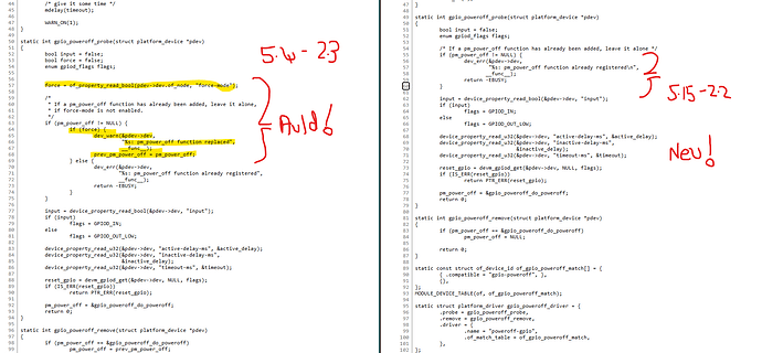
The kernel were using before (https://git.toradex.com/cgit/linux-toradex.git/tree/Documentation/devicetree/bindings/power/reset/gpio-poweroff.txt?h=toradex_5.4-2.1.x-imx)

has the "force-mode" property, whereas the new one.  Does not.

(https://git.toradex.com/cgit/linux-toradex.git/tree/Documentation/devicetree/bindings/power/reset/gpio-poweroff.txt?h=toradex_5.15-2.0.x-imx)

I was looking at this upgrade because I wanted to gain better control of the real-time clock that needed release 5.13 to make it’s driver work properly, and not requiring us to manually configure it.

Can you suggest what I can do ? The poweroff driver won’t work without the force-mode. The RTC driver needs 5.13.

Cheers

Fat Linux

Having a hack at it right now…