Good morning,
On a Colibri IMX7d module with BSP 3 we modified device tree for LCD PADs both CTRL and DATA.
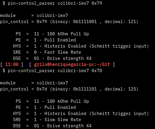
We focused on Slow slew rate set up to reduce EMI.
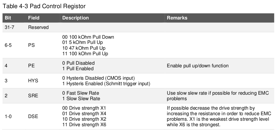
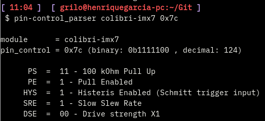
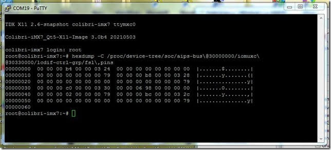
Found those pins on dts and compiled to dtb according to slew rate bit described on IMX7d Reference Manual, placed new dtb on appropriate ubi dev and after a cross check on running dtb byte values post reboot through for example:
hexdump -C /proc/device-tree/soc/aips-bus@30000000/iomuxc@30330000/lcdif-ctrl-grp/fsl,pins
Positively recognized byte changed from 0x79 to 0x7D on what we suppose to be the appropriate registers as depicted in following images:
We saw a very little amount of variation on LDC_CLK wave form, a variation even not measurable on some module while it’s slightly noticeable on others.
I’m aware this question might be more related to the chip itself, but i was wondering if anyone has experienced the same behaviour i describe.
Thanks.
Matteo.