How to enable GPIO1 on X27 to act as an interrupt handler for max14830?

We are trying to add a spi to quad rs232 MAX14830 to an Ixora board with an imx6q SOM. We have succesfully added the device tree part to enable the MAX14830 on spi1 (X27)

&ecspi1 {
status = “okay”;

max148300: max14830@0 {
    compatible = "maxim,max14830";
    reg = <0>;
    clocks = <&xtal_max>;
    clock-names = "xtal";
    interrupt-parent = <&pinctrl_apalis_gpio1>;
    interrupts = <1 IRQ_TYPE_EDGE_FALLING>; // GPIO 1 de X23, FALLING EDGE
    gpio-controller;
    #gpio-cells = <2>;
    spi-max-frequency = <10000000>;
    };

};

The problem is with the “interrupt-parent” and “interrups” portion, we want to use GPIO1 (pin 13 of X27) as the interrupt for this chip, but we don’t know how to reference this pin as an interrupt.

thank you for your help

Hi

You will have to find out the relationship between the Apalis iMX6 X1 GPIO1 pin with the SOC i.MX6 ball and function name and possible its representation in Linux.

Apalis X1         i.MX6 ball         i.MX6 gpio function
GPIO 1            NAND_DATA04        GPIO2_IO04  

So you would need the gpio controller 2, interrupt 4, additionally the pin muxing of said pin must be set to gpio.

pinctrl-names = "default";
pinctrl-0 = <&pinctrl_apalis_gpio1>;
interrupt-parent = <&gpio2>;
interrupts = <4 IRQ_TYPE_LEVEL_LOW>;

With our device tree we already mux the pin here for use through the gpio subsystem, so you would need to remove the muxing there.

With that you should get a new entry in /proc/interrupts.

P.S: I assume you already back ported whatever needed to enable device-tree support for the driver in Linux 3.14.52.

Max

Thank you max, we tryied last night without results because the driver seems to not support the device tree. Waiting for your new kernel release we are testing with mainline kernel 4.6.2. Compiled and running :). The driver has devicetree support but we have no experience with the dts. This are our modifications:

imx6q-apalis-ixora.dts:

/ {
    model = "Toradex Apalis iMX6Q/D Module on Ixora Carrier Board";
    compatible = "toradex,apalis_imx6q-ixora", "toradex,apalis_imx6q",
             "fsl,imx6q";
.......
 xtal_max: xtal20@0 {
        #clock-cells = <0>;
        compatible = "fixed-clock";
        clock-frequency = <3686400>;
        };

};

&ecspi1 {
    status = "okay";

    max148300: max14830@0 {
        compatible = "maxim,max14830";
        reg = <0>;
        clocks = <&xtal_max>;
        clock-names = "xtal";
        gpio-controller;
        #gpio-cells = <2>;
        //spi-max-frequency = <16000000>;
        spi-max-frequency = <10000000>;

        pinctrl-names = "default";
        pinctrl-0 = <&pinctrl_apalis_gpio1>;
        interrupt-parent = <&gpio2>;
        interrupts = <4 IRQ_TYPE_EDGE_FALLING>; // GPIO 1 de X23 [13] -> MXM3 [1] -> NAND_DATA04, GPIO2_IO04, FALLING EDGE
        };
};

.....

&iomuxc {
    /*
     * Mux the Apalis GPIOs
     * GPIO5, 6 used by optional fusion_F0710A kernel module
     */
    pinctrl-names = "default";
    //pinctrl-0 = <&pinctrl_apalis_gpio1 &pinctrl_apalis_gpio2
    pinctrl-0 = <&pinctrl_apalis_gpio2
             &pinctrl_apalis_gpio3 &pinctrl_apalis_gpio4
             &pinctrl_apalis_gpio5 &pinctrl_apalis_gpio6
             &pinctrl_apalis_gpio7 &pinctrl_apalis_gpio8
            >;

    pinctrl_leds_ixora: ledsixoragrp {
        fsl,pins = <
            MX6QDL_PAD_SD1_DAT1__GPIO1_IO17 0x1b0b0
            MX6QDL_PAD_SD1_DAT3__GPIO1_IO21 0x1b0b0
            MX6QDL_PAD_NANDF_D1__GPIO2_IO01 0x1b0b0
            MX6QDL_PAD_NANDF_D2__GPIO2_IO02 0x1b0b0
        >;
    };
};

I don’t know if I understood very well the interrupt definition…

Another question about the SPI bus… To test the MAX14830 we purchased the MAX14830 EVALUATION KIT, is configured by default to use the SPI mode of the chip, so connected the MISO, MOSI, CLOCK and CS directly from the board to the ixora… Do we need some pullup resistors on the four lines?

thank you very much for your great support!

Finally we have a paritally working MAX14830 with the imx6q apalis/ixora boards.

We are using kernel 4.11.0 with this device tree (imx6q-apalis-ixora-zausan.dts)

    #include "imx6q-apalis-ixora.dts"
    
    &iomuxc
    {
        /* pins used on module */
        pinctrl-names = "default";
        pinctrl-0 = <&pinctrl_reset_moci>;
    
        /*
        16      HYS     0   CMOS input
                    1   Schmitt trigger input
    15-14   PUS     00  100 kOhm Pull Down
                    01  47 kOhm Pull Up
                    10  100 kOhm Pull Up
                    11  22 kOhm Pull Up
    13      PUE     0   Keeper enable
                    1   Pull enable             Selection between keeper and pull up/down function
    12      PKE     0   Pull/Keeper Disabled
                    1   Pull/Keeper Enabled     Enable keeper or pull up/down function
    11      ODE     0   Output is CMOS
                    1   Output is open drain
    10-8            Reserved
    7-6     SPEED   00  Reserved
                    01  Low (50 MHz)
                    10  Medium (100 MHz)
                    11  High (200 MHz)
    5-3     DSE     000 output driver disabled (Hi Z)
                    001 240 Ohm
                    010 120 Ohm
                    011 80 Ohm
                    100 60 Ohm
                    101 48 Ohm
                    110 40 Ohm
                    111 34 Ohm                  If possible decrease the drive strength by increasing the resistance in order to reduce EMC problems
    2-1 Reserved
    0       SRE     0   Slow Slew Rate
                    1   Fast Slew Rate          Use slow slew rate if possible for reducing EMC problems
    */

    // 0x100b1  1 00 0 0 0 000 10 110 00 1
    // 0x130b0  1 00 1 1 0 000 10 110 00 0
    // 0x170c1  1 01 1 1 0 000 11 000 00 1
    // 0x000c1  0 00 0 0 0 000 11 000 00 1
    // 0x100c1  1 00 0 0 0 000 11 000 00 1
    pinctrl_ecspi1: ecspi1grp
    {
        fsl,pins = < 
            MX6QDL_PAD_CSI0_DAT6__ECSPI1_MISO 0x100b1 
            MX6QDL_PAD_CSI0_DAT5__ECSPI1_MOSI 0x100b1 
            MX6QDL_PAD_CSI0_DAT4__ECSPI1_SCLK 0x100b1
            /* SPI1 cs */
            MX6QDL_PAD_CSI0_DAT7__GPIO5_IO25 0x000b1
            /* SPI1 cs2 (gpio2 del X27) */
            MX6QDL_PAD_NANDF_D5__GPIO2_IO05 0x000b1

            >;
    };


    pinctrl_apalis_gpio1: gpio2io04grp
    {
        fsl,pins = <
            /* Interrupcion para el MAX14830 (gpio1 del X27) */
            MX6QDL_PAD_NANDF_D4__GPIO2_IO04 0x100c1
            >;
    };

};

&iomuxc {
    /*
     * Mux the Apalis GPIOs
     * GPIO5, 6 used by optional fusion_F0710A kernel module
     */
    pinctrl-names = "default";

    /* ZAUSAN - Quitamos la definicion de gpio1 porque la usamos nosotros para la interrupcion del MAX14830 */
    /* ZAUSAN - Quitamos la definicion de gpio2 porque la usamos nosotros para el CS del MAX14830 */
    pinctrl-0 = <
             &pinctrl_apalis_gpio3 &pinctrl_apalis_gpio4
             &pinctrl_apalis_gpio5 &pinctrl_apalis_gpio6
             &pinctrl_apalis_gpio7 &pinctrl_apalis_gpio8
            >;
};

&ecspi1 {
    /* Añadimos un CS adicional */
    cs-gpios = <
        &gpio5 25 GPIO_ACTIVE_HIGH
        &gpio2 5 GPIO_ACTIVE_HIGH
        >;
    pinctrl-names = "default";
    pinctrl-0 = <&pinctrl_ecspi1>;
    status = "okay";

    gpiom0: gpio@0 {
        compatible = "microchip,mcp23s17";
        #gpio-cells = <2>;
        gpio-controller;
        reg = <0>;
        microchip,spi-present-mask = <0x3>;
        spi-max-frequency = <10000000>;
        #interrupt-cells = <2>;
    };

    max148300: max14830@0 {
        compatible = "maxim,max14830";
        reg = <1>;                          // GPIO2 de X27
        clocks = <&xtal_max>;
        clock-names = "xtal";
        gpio-controller;
        #gpio-cells = <2>;
        spi-max-frequency = <16000000>;
        //spi-max-frequency = <19000000>; // No funciona, detecta 0xd9
        //spi-max-frequency = <20000000>; // No funciona, detecta 0xd9

        /* Interrupcion */
        pinctrl-names = "default";
        interrupt-parent = <&gpio2>;
        interrupts = <4 IRQ_TYPE_LEVEL_LOW>; // GPIO1 de X27, IRQ_TYPE_EDGE_FALLING IRQ_TYPE_LEVEL_LOW
        pinctrl-0 = <&pinctrl_apalis_gpio1>;

        xtal_max: xtal20@0
        {
            compatible = "fixed-clock";
            #clock-cells = <0>;
            clock-frequency = <3686400>;
        };

    };

};

With this configuration the gpio1 on X27 act as interrupt for the MAX14830 and gpio2 on X27 act as second CS for spi1. All works well, four serial ports detected (/dev/ttyMAX[0123]) and the asigned IRQ with number 119.
However we have a problem that we think is caused by the spi speed and/or irq management, the output of ‘cat /proc/cpuinfo’ shows this for IRQ 119:

119:          2          0          0          0  gpio-mxc   4 Edge      spi0.1

As you can see, appears as “Edge” but on the device tree is of type “EDGE_LOW”.
When we run “minicom -D /dev/ttyMAX0” at 119200 8N1 (is a gps receiver sending data continuously, 50 mesages per second) on the console begins to appear:

[   80.786948] max310x_handle_rx: 47 callbacks suppressed
[   80.792128] max310x spi0.1: Possible RX FIFO overrun
[   80.875589] max310x spi0.1: Possible RX FIFO overrun
[   80.958868] max310x spi0.1: Possible RX FIFO overrun
[   81.042031] max310x spi0.1: Possible RX FIFO overrun
[   81.125203] max310x spi0.1: Possible RX FIFO overrun

and the received data from the serial port is incomplete (loss of some characters). The output of “top” is:

top - 10:47:05 up 0 min,  2 users,  load average: 0,60, 0,14, 0,05
Tasks: 134 total,   2 running, 132 sleeping,   0 stopped,   0 zombie
%Cpu0  :  0,0 us, 94,8 sy,  0,0 ni,  0,0 id,  0,0 wa,  0,0 hi,  5,2 si,  0,0 st
%Cpu1  :  0,0 us,  3,8 sy,  0,0 ni, 96,2 id,  0,0 wa,  0,0 hi,  0,0 si,  0,0 st
%Cpu2  :  1,8 us,  8,8 sy,  0,0 ni, 89,5 id,  0,0 wa,  0,0 hi,  0,0 si,  0,0 st
%Cpu3  :  0,0 us,  0,0 sy,  0,0 ni,100,0 id,  0,0 wa,  0,0 hi,  0,0 si,  0,0 st
KiB Mem:   1018096 total,   115876 used,   902220 free,     8448 buffers
KiB Swap:        0 total,        0 used,        0 free.    51148 cached Mem

PID USER      PR  NI    VIRT    RES    SHR S  %CPU %MEM     TIME+ COMMAND                                                                                                                                                                   
257 root        -51   0          0         0         0 R  95,1  0,0   0:17.36 irq/119-spi0.1                                                                                                                                                            
101 root         20   0          0         0         0 S   8,6   0,0   0:01.94 spi0                                                                                                                                                                      
478 root         20   0    4696   2128   1684 R   6,9   0,2   0:00.10 top                                                                                                                                                                       
7 root             20   0          0         0         0 S   3,5   0,0   0:01.09 ksoftirqd/0         

you can see a 95% of cpu load caused by the interrupt.
If we raise the spi-max-frequency above 16000000 the MAX14830 is not detected (MAX14830 spi bus can work at 26000000)

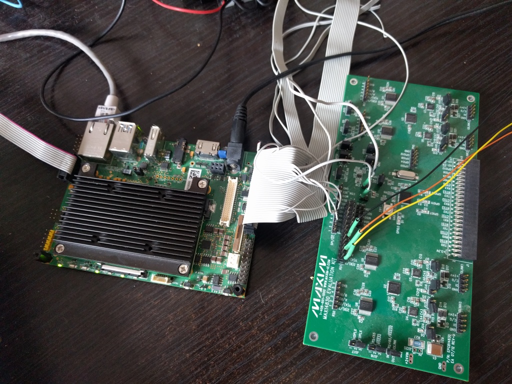
This is our actual setup:

What we don’t know is if the definition for the gpio1 is correct to manage an IRQ. What is the maximum speed of the spi bus?

thank you very much for your great support!