The following is from my software engineer for the system we are developing.
NOTE: As a new user, I am not able to upload the (6) attachments he sent me. Please advise on how I can include those.
System Description
We have a Torizon imx8mp Verdin development board. We need a lot of audio channels, so we have 6 4-channel codecs connected to 6 DIN/DOUT lines from SAI1. The codecs are all AK4619, configured in TDM mode, so BICK is 128 x the frame clock, which is 48 KHz.
I have a single codec connected with the device tree shown at the bottom.
The AK4619 codecs are configured in SPI mode. Each has a different GPIO chip select. I have confirmed for the first 3 that we can access the SPI registers from ecspi1. We wrote a SPI wrapper for the AK4619 driver, so the bulk of the driver is the original I2C-based AK4619 driver, we just removed the I2C and put in a SPI connection instead.
Since the AK4619 will not source the clocks, we have set the CPU to generate them, and all the clocks are routed in parallel to all the codecs. Each codec also gets one RX and one TX data line from the SAI1 set.
We are using toradex_5.15-2.2.x-imx.
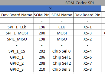
Here are the spi pins in use – GPIO_1 through 3 will be used for SPI chip selects, plus two more pins yet to be identified.
I don’t have a nice chart for the SAI1 pins in use, but I have double-checked them against the list below in pinctrl_sai1.
I am attaching several files:
• ak4619.c – the AK driver with the I2C stuff removed
• ak4619_spi.c – the SPI wrapper for the AK driver
• imx8mp-verdin-dev-icvr.dts – our top-level device tree source
• *.dtsi – DTS includes, mostly unmodified
Question
My question is: how do we setup the device tree for the 5 additional codecs? As said, we have a single codec connected to MX8MP_IOMUXC_SAI5_RXFS__AUDIOMIX_SAI1_TX_DATA00 and MX8MP_IOMUXC_SAI1_RXD0__AUDIOMIX_SAI1_RX_DATA00 working. It appears to be working correctly in TDM mode with 4 channels. But I am at a loss how to engage the SAI1 interface with the additional codecs.
I do have some thoughts, the first of which is I might need to create a ‘dailink’ block for each codec, similar to:
dailink_master_cs0: simple-audio-card,codec2 {
        sound-dai = <&spi1_2>;
        clocks = <&audio_blk_ctrl IMX8MP_CLK_AUDIO_BLK_CTRL_SAI1_MCLK1>;
};
I think I will have to add the additional data lines to the pinctrl_sai1 section.
Thanks,
David
<< snippets of device tree source follow >>
/ {
model = “Toradex Verdin iMX8M Plus on Verdin Development Board - Trident Systems SCC”;
compatible = “trident,scc-dev,”,
“toradex,verdin-imx8mp-nonwifi-dev”,
“toradex,verdin-imx8mp-nonwifi”,
“toradex,verdin-imx8mp”,
“fsl,imx8mp”;
sound {
    status = "disabled";
};

sound_ak4619: sound-ak4619-1 {
        compatible = "simple-audio-card";
        simple-audio-card,bitclock-master = <&dailink_cpu>;
        simple-audio-card,format = "i2s";
        simple-audio-card,frame-master = <&dailink_cpu>;
        simple-audio-card,mclk-fs = <128>;
        simple-audio-card,name = "icvr-ak4619-0";
        simple-audio-card,routing =
                "Line Out", "AOUT1L",
                "Line Out", "AOUT1R",
                "Line Out", "AOUT2L",
                "Line Out", "AOUT2R",
                "AIN1L", "Line In",
                "AIN1R", "Line In",
                "AIN2L", "Line In",
                "AIN2R", "Line In";
        simple-audio-card,widgets =
            "Line Out", "Line Out",
            "Line", "Line In";

        status = "okay";

        dailink_master_cs0: simple-audio-card,codec0 {
                sound-dai = <&spi1_0>;
                clocks = <&audio_blk_ctrl IMX8MP_CLK_AUDIO_BLK_CTRL_SAI1_MCLK1>;
        };

        dailink_cpu: simple-audio-card,cpu {
                sound-dai = <&sai1>;
                convert-channels = <4>;
                dai-tdm-slot-num = <4>;
                dai-tdm-slot-width = <32>;
                clocks = <&audio_blk_ctrl IMX8MP_CLK_AUDIO_BLK_CTRL_SAI1_MCLK1>;
                pinctrl-names = "default";
                pinctrl-0 = <&pinctrl_sai1>;
        };
};
…
};
&ecspi1 {
#address-cells = <1>;
#size-cells = <0>;
status = “okay”;
cs-gpios = <&gpio1 0 GPIO_ACTIVE_LOW>, <&gpio5 9 GPIO_ACTIVE_LOW>, <&gpio1 1 GPIO_ACTIVE_LOW>;
spi1_0: cs0@0 {
        reg = <0>;
        compatible = "ak4619";

        spi-max-frequency = <1000000>;
        spi-cpha;
        spi-cpol;
        status = "disabled";
};

spi1_1: cs1@1  {
        reg = <1>;
        compatible = "ak4619";

        spi-max-frequency = <1000000>;
        spi-cpha;
        spi-cpol;
        status = "okay";
};

spi1_2: cs2@2 {
        reg = <2>;
        compatible = "ak4619";

        spi-max-frequency = <1000000>;
        spi-cpha;
        spi-cpol;
        status = "disabled";
};
};
…
/* Verdin I2S_1 */
&sai1 {
assigned-clocks = <&clk IMX8MP_CLK_SAI1>;
assigned-clock-parents = <&clk IMX8MP_AUDIO_PLL1_OUT>;
assigned-clock-rates = <24576000>;
fsl,sai-mclk-direction-output;
status = “okay”;
};
…
&pinctrl_sai1 {
fsl,pins =
<MX8MP_IOMUXC_SAI1_MCLK__AUDIOMIX_SAI1_MCLK 0x96>, /* SODIMM 38 /
<MX8MP_IOMUXC_SAI1_RXD0__AUDIOMIX_SAI1_RX_DATA00 0x1d6>, / SODIMM 36 /
<MX8MP_IOMUXC_SAI5_MCLK__AUDIOMIX_SAI1_TX_BCLK 0x1d6>, / SODIMM 30 /
<MX8MP_IOMUXC_SAI5_RXD1__AUDIOMIX_SAI1_TX_SYNC 0x1d6>, / SODIMM 32 /
<MX8MP_IOMUXC_SAI5_RXFS__AUDIOMIX_SAI1_TX_DATA00 0x96>; / SODIMM 34 */
};
/*
*/
&iomuxc {
pinctrl-names = “default”;
pinctrl-0 = <&pinctrl_gpio1>, <&pinctrl_gpio2>,
<&pinctrl_gpio3>, <&pinctrl_gpio4>,
<&pinctrl_gpio8>,
<&pinctrl_gpio_hog1>, <&pinctrl_gpio_hog2>, <&pinctrl_gpio_hog3>,
<&pinctrl_hdmi_hog>;
};