Hi @geopaxpvtltd ,
I got it to partially work using the following dts
What exactly is not completely working? Are the interrupts working, or you don’t need them?
Could you explain how it started working? I am using the i2c1 that is exposed byt the verdin modul. why did it work with &i2c4?
I think you physically connected the IMU to the i2c4 pins from the start and you’re getting confused about the naming scheme of the peripherals. In the Verdin iMX8M Mini datasheet there’s the Verdin Standard Function names which is how we name the pins that have common functions for the whole Verdin SoM family.
But there’s also the pin Ball name, which is the name given by NXP and the device tree nodes are usually named after it.
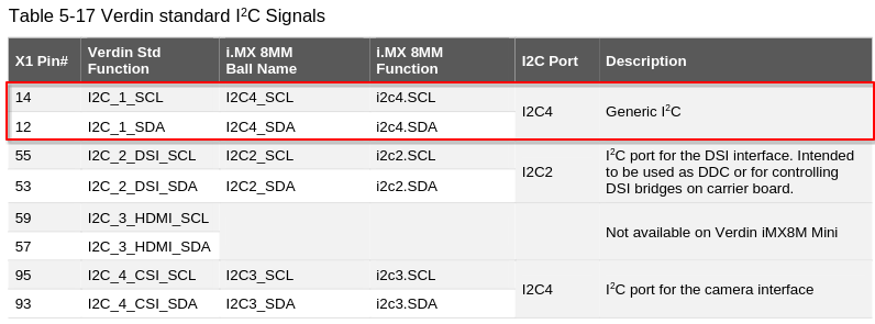
The Verdin Standard names for the pins don’t necessarily follow the same peripheral numbering used in the ball name, as you can see in this table from the Verdin iMX8M Mini datasheet:
So the Verdin standard I2C1 pins actually correspond to the i2c4 node. The Verdin iMX8M Mini device tree even has a comment hinting at this:
/* Verdin I2C_1 */
&i2c4 {
	clock-frequency = <400000>;
	pinctrl-names = "default", "gpio";
	pinctrl-0 = <&pinctrl_i2c4>;
	pinctrl-1 = <&pinctrl_i2c4_gpio>;
	scl-gpios = <&gpio5 20 (GPIO_ACTIVE_HIGH | GPIO_OPEN_DRAIN)>;
	sda-gpios = <&gpio5 21 (GPIO_ACTIVE_HIGH | GPIO_OPEN_DRAIN)>;
[...]
and what difference do the address cells and size cells makes? and where does one get these values from?
These are generic device tree properties used by all addressable devices. Basically these two tell how fill the reg property. You can see more details here:
Each device sets these fields differently and you need to follow its corresponding devicetree binding documentation found in the kernel sources.
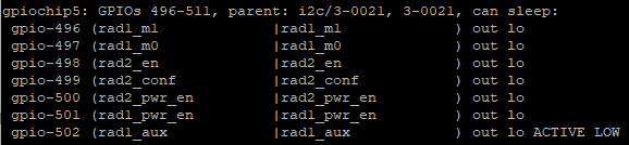
it says failed to register i2c client pcal6416 but the gpios seem to be working? also, the imu appears in the iio devices
If you take a look at the Verdin iMX8M Mini device tree sources you can see that there actually is a GPIO expander already defined at I2C4 address 0x21 called gpio-expander:
&i2c4 {
clock-frequency = <400000>;
pinctrl-names = "default", "gpio";
pinctrl-0 = <&pinctrl_i2c4>;
pinctrl-1 = <&pinctrl_i2c4_gpio>;
scl-gpios = <&gpio5 20 (GPIO_ACTIVE_HIGH | GPIO_OPEN_DRAIN)>;
sda-gpios = <&gpio5 21 (GPIO_ACTIVE_HIGH | GPIO_OPEN_DRAIN)>;
gpio_expander_21: gpio-expander@21 {
compatible = "nxp,pcal6416";
#gpio-cells = <2>;
gpio-controller;
reg = <0x21>;
vcc-supply = <®_3p3v>;
status = "disabled";
};
[...]
Incidentally, this expander refers to the same nxp,pcal6416 compatible field. I think the GPIO expander node defined in your overlay is getting probed first, then when gpio-expander tries to initialize it naturally fails as the 0x21 address is already in use.
This probably explains the ‘fail to register i2c client’ messages you saw.
Best regards,
Lucas Akira