Im working on adapting some code available for the raspberry pi designed to read data from Inertial Measurement Units on a NAVIO2 Board connected through the x20 extension connector.
I have successfully enabled spidev2.0 as it shows here 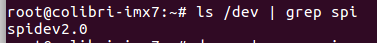
I am having problems though because the previous code used spidev0.1 so I thought after enabling spidev2.0 it should be as simple as swapping it for spidev2.0 on the code since its supposed to be compatible with raspberry shields.But what happens is that the receive buffer is not getting anything back.
My adaptation of the code is available here:
hi @iagosilvestre
Can you share the connection diagram showing which SODIMM pins you are using of the SPI communication?
Which code is running on iMX7 for the SPI Communication?
Best regards, Jaski
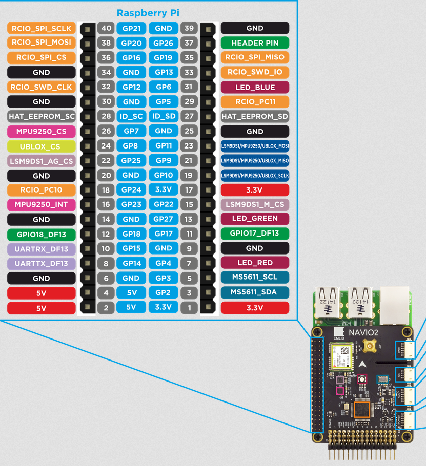
This is the pinout of the NAVIO2 Board which I connected on the x20, the pins used for SPI I believe are 23,21,19 which would translate into beign SODIMM pins 88, 90 and 92 . The code running is an adaptation of the AccelGyroMag example developed for Raspberry Pi, im gonna share the main code and the 2 most important headers link text
This pin-out is not compatible with Raspberry Pi hat connector, MOSI is switched with SCLK
https://www.raspberrypi.org/documentation/usage/gpio/README.md
Other issue is the CS pin for the IMU, pin 15 on the rpi hat connector is shared with lcd backlight enable, to configure it as a spi cs, you’ll need to modify the imx7 aster devicetree appropriately. Rpi Hat standard CS0/CS1 for SPI0 is suppose to be on pin 24 and 26.
But I am using it without error on the Raspberry Pi 3Model B, the readings of both IMU’s are correct, I imagine then it would be about the CS pins configurations on the device tree, are there any guides on modifying x20 connector configs?
Hi @iagosilvestre
Thanks for the file and the information about the pins. The pins 19, 21, 23 are used for SPI Communication and the schematic is as following:
- 19 → MOSI
- 21 → MISO
- 23 → SCLK
It does not seem to be the same on the NAVIO Board. So how did you connect navio2 to aster carrier board.
. Concerning the code, did you get any error back? You could also the Spi test code to check if the Spi Communication is working in general.
yeah, you will need to compile and flash a custom device tree with correct muxing. The device tree customization and the pin muxing is explained here.